Transcription of CHAPTER 26 WIND LOADS: GENERAL REQUIREMENTS
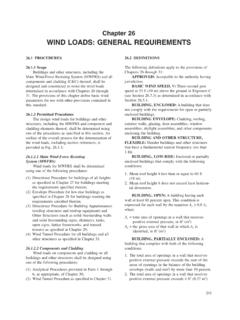
1 MINIMUM design LOADS251 Surface Roughness B: Urban and suburban areas, wooded areas, or other terrain with numerous closely spaced obstructions having the size of single-family dwellings or Roughness C: Open terrain with scattered obstructions having heights generally less than 30 ft ( m). This category includes fl at open country and Roughness D: Flat, unobstructed areas and water surfaces. This category includes smooth mud fl ats, salt fl ats, and unbroken Exposure CategoriesExposure B: For buildings with a mean roof height of less than or equal to 30 ft ( m), Exposure B shall apply where the ground surface roughness, as defi ned by Surface Roughness B, prevails in the upwind direction for a distance greater than 1,500 ft (457 m).
2 For buildings with a mean roof height greater than 30 ft ( m), Exposure B shall apply where Surface Roughness B prevails in the upwind direction for a distance greater than 2,600 ft (792 m) or 20 times the height of the building , whichever is C: Exposure C shall apply for all cases where Exposures B or D do not D: Exposure D shall apply where the ground surface roughness, as defi ned by Surface Roughness D, prevails in the upwind direction for a distance greater than 5,000 ft (1,524 m) or 20 times the building height, whichever is greater. Exposure D shall also apply where the ground surface roughness immediately upwind of the site is B or C, and the site is within a distance of 600 ft (183 m) or 20 times the building height, whichever is greater, from an Expo-sure D condition as defi ned in the previous a site located in the transition zone between exposure categories, the category resulting in the largest wind forces shall be.
3 An intermediate exposure between the preceding categories is permitted in a transition zone provided that it is determined by a rational analysis method defi ned in the recognized Exposure Directional Procedure ( CHAPTER 27)For each wind direction considered, wind loads for the design of the MWFRS of enclosed and partially enclosed buildings using the Directional Procedure of CHAPTER 27 shall be based on the exposures as defi ned in Section Wind loads for the design of open buildings with monoslope, pitched, or troughed free roofs shall be based on the expo-sures, as defi ned in Section , resulting in the highest wind loads for any wind direction at the site.
4 Envelope Procedure ( CHAPTER 28)Wind loads for the design of the MWFRS for all low-rise buildings designed using the Envelope Procedure of CHAPTER 28 shall be based on the exposure category resulting in the highest wind loads for any wind direction at the Directional Procedure for building Appurtenances and Other Structures ( CHAPTER 29)Wind loads for the design of building appurte-nances (such as rooftop structures and equipment) and other structures (such as solid freestanding walls and freestanding signs, chimneys, tanks, open signs, lattice frameworks, and trussed towers) as specifi ed in CHAPTER 29 shall be based on the appropriate exposure for each wind direction Components and Cladding ( CHAPTER 30)
5 design wind pressures for components and cladding shall be based on the exposure category resulting in the highest wind loads for any wind direction at the TOPOGRAPHIC Wind Speed-Up over Hills, Ridges, and EscarpmentsWind speed-up effects at isolated hills, ridges, and escarpments constituting abrupt changes in the GENERAL topography, located in any exposure category, shall be included in the design when buildings and other site conditions and locations of structures meet all of the following conditions:1. The hill, ridge, or escarpment is isolated and unobstructed upwind by other similar topographic features of comparable height for 100 times the height of the topographic feature (100H) or 2 mi ( km), whichever is less.
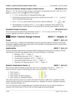
6 This distance shall be measured horizontally from the point at which the height H of the hill, ridge, or escarpment is The hill, ridge, or escarpment protrudes above the height of upwind terrain features within a 2-mi ( ) radius in any quadrant by a factor of two or The structure is located as shown in Fig. in the upper one-half of a hill or ridge or near the crest of an 2514/14/2010 11:04:32 AMCHAPTER 26 WIND LOADS: GENERAL REQUIREMENTS252 Topographic Factor, Multipliers for Exposure C K1 Multiplier K2 Multiplier K3 Multiplier H/Lh2-D Ridge 2-D Escarp. 3-DAxisym.
7 Hill x/Lh 2-D Escarp. All Other Casesz/Lh 2-D Ridge Axisym. Hill
8
9 Notes: 1. For values of H/Lh, x/Lh and z/Lh other than those shown, linear interpolation is permitted.
10 2. For H/Lh > , assume H/Lh = for evaluating K1 and substitute 2H for Lh for evaluating K2 and Multipliers are based on the assumption that wind approaches the hill or escarpment along the direction of maximum slope. 4. Notation: H: Height of hill or escarpment relative to the upwind terrain, in feet (meters). Lh: Distance upwind of crest to where the difference in ground elevation is half the height of hill or escarpment, in feet (meters). K1: Factor to account for shape of topographic feature and maximum speed-up effect. K2: Factor to account for reduction in speed-up with distance upwind or downwind of crest.