Transcription of CHAPTER 3
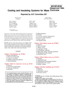
1 CHAPTER 3 Building Walls Have bucks and stub outs ready. Like masonry, start from the corner and stack toward the middle. 11 CHAPTER 3: BUILDING WALLS This CHAPTER addresses design aspects of the use of SmartBlock insulating forms in the construction of a building wall. SmartBlock SF10 insulating forms can be used in exterior or interior bearing or non-bearing walls to an unsupported height of 10 ft. for 2 story construction in accordance with Finding #2 of ICBO ES Evaluation Report No. 4572. Higher building walls can be constructed with the SmartBlock VWF Series forms or with the SF10 Series by specific design by an architect or engineer. This manual contains details and tables for use of SmartBlock SF10 Series insulating forms in building wall construction in accordance with ICBO ES Evaluation Report No.
2 4572, and BOCA Research Report No. 95-46. Footings Building walls constructed with SmartBlock insulating forms require an increase in spread footings sizes compared with conventional wood frame construction, due to the increased weight of concrete walls. This increased size acts to and compensate for shear at the wall plane at the footing. In tables A, B, C, D and E in Design Section of CHAPTER 9, soil bearing pressures are assumed to be 1000 psf. Individual soils analysis may reduce or increase these sizes. Reinforcing Steel Suggested reinforcing steel requirements, sizes and spacings are identified throughout in this manual. Reinforcement parameters should be in accordance with specific project design requirements.
3 Ledgers In typical reinforced concrete or masonry construction, floors are supported by the use of a ledger (see Details , and ). Before the pour, to avoid cantilevering the anchor bolts used in the ledger, the SmartBlock insulating forms should be cut to allow proper surrounding of "J" bolts with concrete. Due to the thickness of the concrete cell, embedment requirements should be addressed in all ledgers and ledger bolt designs. Horizontal diaphragm shear may be transferred to the wall at this point and should be designed for each project. To facilitate placement of reinforcing steel, all door and window openings should be constructed as fabrication proceeds rather than waiting until forming is complete. UBC requires that two No.
4 5 rebars are placed vertically and horizontally at each opening and the ends of the bars should extend a minimum of 24 beyond the corners of the opening. In the case of the restricted area past the corner of an opening, the bar may be bent to tie to the nearest horizontal or vertical reinforcing bar. Lintels Lintels over openings may be constructed as shown in Detail No. The distance between the top and bottom reinforcing steel governs the strength of the lintel so rebar placement is critical. If foam bridging in the SF10 Series restricts placement of rebar around lintels, VWF Series may be substituted. All lintel applications must be reviewed and approved by the project architect or engineer. Plates The top plate may be installed in the same manner as common with other construction methods.
5 The plate should consist of PTDF, foundation grade redwood or an approved equal. Due to shear forces at this level, anchor bolt spacings are designed depending on the size of plate used. Refer to table No. 25-F in the UBC for specific design parameters. Applications must be reviewed for compliance with local codes and conditions. Lateral Design Lateral design is addressed in various details showing typical nailing, clips, anchor bolts, etc. used in the field for shear transfer (see CHAPTER 16 - Details , , , , , , , and ). These details show possible solutions that must be designed in connection with lateral design. Each project must be analyzed individually since specific building design and local codes govern parameters of lateral design.
6 Structural Design Unlike masonry walls that derive some structural value from concrete masonry units (CMU s), the SmartBlock insulating form contributes no structural value to the wall system. The structural strength of SmartBlock insulating form walls is provided solely by the reinforced concrete structure contained within the SmartBlock insulating forms. SF10 Series Section of this manual contains a table of the allowable (factored) bending moments, lateral loads and axial loads of a concrete wall formed with SF10 Series insulating forms along with the supporting calculations for use by the design engineer and building officials. The structural design capacities of the 6 inch wide concrete wall contained within the SF10 Series insulating forms are in accordance with CHAPTER 19 of the 1997 UBC.
7 However, the structural capacity of the SF10 Series wall is slightly reduced (compared to a solid 6 inch wide concrete wall) because of the displacement of concrete by the 2 inch by 3 inch EPS bridges spaced on a 10 inch by 10 inch grid pattern. Flexural Design Capacity Since the 2 inch wide EPS bridges in the SF10 Series block are spaced 10 inches apart horizontally, the effective width or b dimension of a SmartBlock insulating form wall is reduced 25% as compared to a solid concrete wall. Therefore, the b dimension per lineal foot of wall in the following equation: a = Asfy / .85f cb 15is 9 inches in lieu of the standard 12 inch dimension customary for wall design. Once the modified b dimension is calculated, calculation of the allowable moment is identical to a solid concrete wall design using the following equation: fM = fAsfy (d - a/2) Allowable Lateral Loads Similar to flexural design, the b dimension in the following equation: fV = f2 f c (b)d is 9 inches in lieu of the customary 12 inches for solid wall design.
8 Allowable Axial Loads For the 6 inch wide wall, the presence of the EPS bridges effects the axial load capacity of the wall by reducing Ag in the following equation: fP = .55ff cAg[1 - (Klc/32h)2] Ag for the SF10 Series wall is square inches ( inches x 9 inches) in lieu of 78 square inches ( inches x 12 inches) for a solid 6 inch wall. VWF Series The VWF Series blocks are connected by plastic ties similar in size to ties used for conventionally formed concrete. Therefore, the structural capacities of walls using the VWF Series blocks are the same as for other concrete forming methods. These capacities may be calculated in accordance with CHAPTER 19 of the 1997 UBC for concrete wall widths of 3 inches, 5 inches, 7 inches, 9 inches and 11 inches.
9