Transcription of Chapter 3 Basic Plasma Physics - NASA
1 37 Chapter 3 Basic Plasma Physics Introduction Electric propulsion achieves high specific impulse by the acceleration of charged particles to high velocity. The charged particles are produced by ionization of a propellant gas, which creates both ions and electrons and forms what is called a Plasma . Plasma is then a collection of the various charged particles that are free to move in response to fields they generate or fields that are applied to the collection and, on the average, is almost electrically neutral. This means that the ion and electron densities are nearly equal, ni ne, a condition commonly termed quasi-neutrality. This condition exists throughout the volume of the ionized gas except close to the boundaries, and the assumption of quasi-neutrality is valid whenever the spatial scale length of the Plasma is much larger than the characteristic length over which charges or boundaries are electrostatically shielded, called the Debye length.
2 The ions and electrons have distributions in energy usually characterized by a temperature Ti for ions and Te for electrons, which are not necessarily or usually the same. In addition, different ion and electron species can exist in the Plasma with different temperatures or different distributions in energy. Plasmas in electric propulsion devices, even in individual parts of a thruster, can span orders of magnitude in Plasma density, temperature, and ionization fraction. Therefore, models used to describe the Plasma behavior and characteristics in the thrusters must be formed with assumptions that are valid in the regime being studied. Many of the Plasma conditions and responses in thrusters can be modeled by fluid equations, and kinetic effects are only important in specific instances. There are several textbooks that provide very comprehensive introductions to Plasma Physics [1 3] and the generation of ion beams [4].
3 This Chapter is 38 Chapter 3 intended to provide the Basic Plasma Physics necessary to understand the operation of ion and Hall thrusters. The units used throughout the book are based on the International System (SI). However, by convention we will occasionally revert to other metric units (such as A/cm2, mg/s, etc.) commonly used in the literature describing these devices. Maxwell s Equations The electric and magnetic fields that exist in electric propulsion plasmas obey Maxwell s equations formulated in a vacuum that contains charges and currents. Maxwell s equations for these conditions are E= o ( ) E= B t ( ) B=0 ( ) B= oJ+ o E t , ( ) where is the charge density in the Plasma , J is the current density in the Plasma , and o and o are the permittivity and permeability of free space, respectively.
4 Note that and J comprise all the charges and currents for all the particle species that are present in the Plasma , including multiply charged ions. The charge density is then =qsns=eZni ne()s , ( ) where qs is the charge state of species s, Z is the charge state, ni is the ion number density, and ne is the electron number density. Likewise, the current density is J=qsnsvs=eZnivi neve()s , ( ) where vs is the velocity of the charge species, vi is the ion velocity, and ve is the electron velocity. For static magnetic fields B t=0(), the electric field can be expressed as the gradient of the electric potential, Basic Plasma Physics 39 E= , ( ) where the negative sign comes from the convention that the electric field always points in the direction of ion motion.
5 Single Particle Motions The equation of motion for a charged particle with a velocity v in a magnetic field B is given by the Lorentz force equation: F=mdvdt=qE+v B(). ( ) Particle motion in a magnetic field in the z direction for the case of negligible electric field is found by evaluating Eq. ( ): m vx t=qBvym vy t= qBvxm vz t=0. ( ) Taking the time derivative of Eq. ( ) and solving for the velocity in each direction gives 2vx t2=qBm vy t= qBm 2vx 2vy t2= qBm vx t= qBm 2vy. ( ) These equations describe a simple harmonic oscillator at the cyclotron frequency: c=qBm. ( ) For electrons, this is called the electron cyclotron frequency.
6 The size of the particle orbit for finite particle energies can be found from the solution to the particle motion equations in the axial magnetic field. In this case, the solution to Eq. ( ) is 40 Chapter 3 vx,y=v ei ct. ( ) The equation of motion in the y-direction in Eq. ( ) can be rewritten as vy=mqB vx t=1 c vx t. ( ) Utilizing Eq. ( ), Eq. ( ) becomes vy=1 c vx t=iv ei ct= y t. ( ) Integrating this equation gives y yo=v cei ct. ( ) Taking the real part of Eq. ( ) gives y yo=v ccos ct=rL cos ct, ( ) where rL=v / c is defined as the Larmor radius. A similar analysis of the displacement in the x direction gives the same Larmor radius 90 degrees out of phase with the y-direction displacement, which then with Eq.
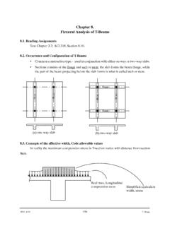
7 ( ) describes the particle motion as a circular orbit around the field line at xo and yo with a radius given by rL. The Larmor radius arises from very simple Physics . Consider a charged particle of mass, m, in a uniform magnetic field with a velocity in one direction, as illustrated in Fig. 3-1. The charge will feel a Lorentz force F=qv B. ( ) Since the charged particle will move under this force in circular orbits in the v B direction, it feels a corresponding centripetal force such that Basic Plasma Physics 41 Fig. 3-1. Positively charged particle moving in a uniform vertical magnetic field. Fc=qv B=mv 2r, ( ) where r is the radius of the cycloidal motion in the magnetic field. Solving for the radius of the circle gives r=rL=mv qB, ( ) which is the Larmor radius.
8 The Larmor radius can be written in a form simple to remember: rL=v c=1B2mV e, ( ) using 12mv 2=eV for the singly charged particle energy in the direction perpendicular to the magnetic field. The direction of particle gyration is always such that the induced magnetic field is opposite in direction to the applied field, which tends to reduce the applied field, an effect called diamagnetism. Any particle motion along the magnetic field is not affected by the field, but causes the particle motion to form a helix along the magnetic field direction with a radius given by the Larmor radius and a pitch given by the ratio of the perpendicular to parallel velocities. Next consider the situation in Fig. 3-1, but with the addition of a finite electric field perpendicular to B. In this case, E is in some direction in the plane of the page.
9 The equation of motion for the charged particle is given by Eq. ( ). Considering the drift to be steady-state, the time derivative is equal to zero, and Eq. ( ) becomes E= v B. ( ) Taking the cross product of both sides with B gives E B= v B() B=vB2 BB v(). ( ) The dot product is in the direction perpendicular to B, so the last term in Eq. ( ) is equal to zero. Solving for the transverse velocity of the particle gives 42 Chapter 3 v=E BB2 vE, ( ) which is the E cross B drift velocity. In this case, the drift is in the direction perpendicular to both E and B, and arises from the cycloidal electron motion in the magnetic field being accelerated in the direction of E and decelerated in the direction of E.
10 This elongates the orbit on one-half cycle and shrinks the orbit on the opposite half cycle, which causes the net motion of the particle in the E B direction. The units of the E B velocity are vE=E [V/m]B [tesla] (m/s). ( ) Finally, consider the situation of a particle gyrating in a magnetic field that is changing in magnitude along the magnetic field direction z . This is commonly found in electric propulsion thrusters relatively close to permanent magnets or electromagnetic poles-pieces that produce fields used to confine the electrons. Since the divergence of B is zero, Eq. ( ), the magnetic field in cylindrical coordinates is described by 1r rrBr()+ Bz z=0. ( ) Assuming that the axial component of the field does not vary significantly with r and integrating yields the radial component of the magnetic field with respect to r, Br r2 Bz z.