Transcription of Chapter 3 Culvert Design - Washington State Department of ...
1 Hydraulics Manual M Page 3-1 April 2019 Chapter 3 Culvert Design3-1 IntroductionA Culvert is a closed conduit under a roadway or embankment used to maintain flow from a natural channel or drainage ditch. A Culvert shall convey flow without causing damaging backwater, excessive flow constriction, or excessive outlet addition to determining the Design flows and corresponding hydraulic performance of a particular Culvert , other factors can affect the ultimate Design of a Culvert and should be taken into consideration. These factors can include the economy of alternative pipe materials and sizes, horizontal and vertical alignment, environmental concerns, and necessary Culvert end some situations, the hydraulic capacity may not be the only consideration for determining the size of a Culvert opening. Fish passage requirements often dictate a different type of crossing than would normally be used for hydraulic capacity. Wetland preservation may require upsizing a Culvert or replacing a Culvert with a bridge.
2 Excessive debris potential may also require an increase in Culvert size. Bridges and fish passage culverts are covered in more detail in Chapter 7 but require a PEO approved by the HQ Hydraulics Section to complete the guidance in this Chapter applies only to non-fish-bearing channels. For culverts associated with fish-bearing channels, refer to Chapter 7. Section 3-2 discusses the data acquisition and documentation required when designing culverts. Culvert Design considerations are discussed in detail in Section 3-3, and various end treatments are discussed in Section 3-4. Section 3-5 covers other miscellaneous Design considerations that have not been previously Culvert Design Hydraulic ReportsThe PEO shall collect field data and perform an engineering analysis as described in Section and Culverts in this size range shall be referred to on the contract plan sheets as Schedule ____ Culv. Pipe ____ in. Diam. The PEO is responsible for listing all acceptable pipe alternates based on site conditions.
3 The decision regarding which type of pipe material to be installed at a location will be left to the contractor unless a specific material type is called out in the plans and justification is provided in the hydraulic report. See Chapter 8 for a discussion on schedule pipe and acceptable alternates. Culverts larger than 48 inches in diameter or span will be included as part of a specialty report and are required to be designed by either the HQ Hydraulics Section or by a licensed engineer approved by the HQ Hydraulics Section, as outlined in Chapter 1. In addition to standard Culvert Design , the HQ Hydraulics Section can assist in the Design of any unique Culvert installation. The requirements for these structures will vary, and it is recommended that the HQ Hydraulics Section be contacted early in the Design phase to determine what information will be necessary to complete the engineering 3 Culvert DesignPage 3-2 Hydraulics Manual M April Required Field DataInformation and field data required to complete an engineering analysis for all new Culvert installations or draining an area requiring a Culvert shall be part of the hydraulic report and include the items that follow:1.
4 Topographic map showing the contours and the outline of the drainage Description drainage area ground Fish passage requirement, if applicable see Chapter Soils investigation per WSDOT s Design Proposed roadway profile and alignment in the vicinity of the Proposed roadway cross section at the Corrosion zone location, pH, and resistivity of the Investigate a sufficient distance upstream and downstream and any other unique features that can affect Design , such as low-lying structures that could be affected by excessive headwater debris, anticipated sediment transport, and other consideration discussed in Section an existing Culvert (s) does not have a history of problems and only needs to be extended or replaced, it is not necessary to gather all the information listed above to determine if it is adequately sized for the flows it receives. Attaining the history of problems at an existing Culvert site may be sufficient to complete the analysis.
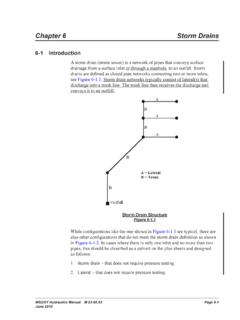
5 Figure 3-1 is a general outline showing the information and field data requirements for a hydraulic report and specialty report. For non-fish-bearing channels with spans between 4 and 20 feet, use the Culvert Design in this Chapter . If the channel is fish-bearing and/or the span is greater than 20 feet, refer to Chapter 7 for further 3-1 Field Data Requirements for Hydraulic Reports and Specialty ReportsInformation and Field DataNew Culvert SiteExtending or ReplacingSpecialty Report1. Topographic surveyROR2. Ground cover descriptionROR3. Ground soil investigationROR4. Proposed roadway profile and alignmentROR5. Proposed roadway cross sectionROR6. Corrosion Zone, pH, resistivity(1)R(1)O(1)R(1)7. Unique featuresRORN otes:O = optionalR = required(1)Only required if replacing with dissimilar material. Culvert Design Chapter 3 Hydraulics Manual M Page 3-3 April Engineering AnalysisCollected field data will be used to perform an engineering analysis. The intent of the engineering analysis is to ensure that the PEO considers several issues, including flow capacity requirements, foundation conditions, embankment construction, runoff conditions, soil characteristics, stream characteristics, potential construction problems, estimated cost, environmental concerns, and any other factors that may be involved and pertinent to the Design .
6 Additional analysis may be required, if a Culvert is installed for flood equalization, to verify that the difference between the floodwater levels is less than one inch on either side of the Culvert . The PEO should contact the HQ Hydraulics Section for further guidance on flood equalization. Other miscellaneous Design considerations for culverts are discussed in Section the engineering analysis is completed, it will be part of the hydraulic report and shall include:1. Culvert hydrology and hydraulic calculations, as described in Section 3-3 and Figure Proposed roadway stationing of the Culvert Culvert Culver diameter. 5. Culvert material. 6. Headwater depths, water surface elevations, and flow rates (Q) for the Design flow event (generally the 25-year event and the 100-year flow event). 7. Proposed roadway cross section and roadway profile, demonstrating the maximum and minimum height of fill over the Appropriate end treatment as described in Section Hydraulic features of downstream controls, tailwater, or backwater (storage) conditions.
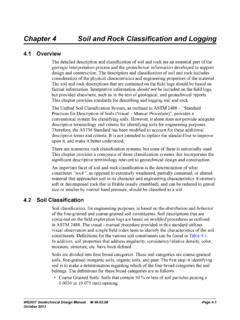
7 The information needed for replacement or extension of existing culverts is not the same as that required for new culverts (see Figure 3-2). For a more in detailed diagnostic about what is required for a specialty report for water crossings, see Chapter 3-2 Information for the Hydraulics and Specialty Reports for New Culverts and for Extending/Replacing Existing CulvertsEngineering Analysis ItemsNew Culvert SiteExtending or ReplacingSpecialty Report1. Culvert hydraulic and hydrology calculationsROR2. Roadway stationing at culvertRRR3. Culvert and stream profileROR4. Culvert length and sizeRRR5. Culvert materialRRR6. Hydraulic detailsROR7. Proposed roadway detailsROR8. End treatmentRRR9. Hydraulic featuresRORN otes:O = optionalR = requiredChapter 3 Culvert DesignPage 3-4 Hydraulics Manual M April 20193-3 Hydraulic Design of CulvertsA complete theoretical analysis of the hydraulics of a particular Culvert installation is time-consuming and complex. Flow conditions vary from Culvert to Culvert and can also vary over time for any given Culvert .
8 The barrel of the Culvert may flow full or partially full depending upon upstream and downstream conditions, barrel characteristics, and inlet geometry. However, under most conditions, a simplified procedure is sufficient to determine the type of flow control and corresponding headwater elevation that exist at a Culvert during the chosen Design flow. This section includes excerpts from the FHWA s Hydraulic Design Series (HDS) No. 5, Hydraulic Design of Highway Culverts. The PEO should refer to the Hydraulics Manual for detailed information on the theory of Culvert flow or reference an appropriate hydraulics textbook for unusual situations. The HQ Hydraulics Section is also available to provide Design general procedure to follow when designing a Culvert for a span width of less than 20 feet is summarized in the steps below. Culvert spans over 20 feet are considered bridges and any hydraulic Design for bridges is the responsibility of the HQ Hydraulics Section, see Section for further Calculate the Culvert Design flows (Section ).
9 2. Determine the allowable headwater elevation (Section ).3. Determine the tailwater elevation at the Design flow (Section ).4. Determine the type of control that exists at the Design flow(s), either inlet control or outlet control (Section ).5. Calculate outlet velocities (Section ). Culvert Design FlowThe first step in designing a Culvert is to determine the Design flows to be used. The flow from the basin contributing to the Culvert can be calculated using the methods described in Chapter 2. Generally, culverts will be designed to meet criteria for two flows: the 25-year event and the 100-year event. If fish passage is a requirement at a Culvert location, contact the HQ Hydraulics Section (see Chapter 7). Guidelines for temporary culverts are described further in Section The PEO will be required to analyze each Culvert at each of the Design flows, ensuring that the appropriate criteria are Additional Requirement for Culverts over 20 FeetOnce a Culvert exceeds 20 feet along the centerline of the roadway, it is defined as a bridge and all hydraulic analysis on bridges are the responsibility of the HQ Hydraulics Section (see Chapter 1).
10 The federal definition of a bridge is a structure, including supports, erected over a depression or obstruction, such as water, highway, or railway, and having a track or passageway for carrying traffic or other moving loads with a clear span, as measured along the centerline of the roadway, equal to or greater than 20 feet. Culvert Design Chapter 3 Hydraulics Manual M Page 3-5 April 2019 The interior cell walls of a multiple box are ignored as well as the distance between the multiple pipes if the distance between pipes is less than D/2 ( , a 16-foot Culvert on a 45-degree skew is a bridge; a 10-foot Culvert on a 60-degree skew is a bridge; and three 6-foot pipes 2 feet apart is a bridge). The two primary types of hydraulic analysis performed on bridges are backwater and scour. As noted above, all hydraulic analysis of bridges is performed by the HQ Hydraulics Section; however, it is the responsibility of the PEO to gather field information for the analysis.