Transcription of Chapter 3 DESIGN CONCEPT FOR PRECAST SYSTEM
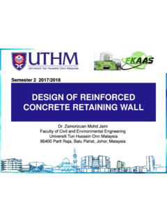
1 23 Chapter 3 DESIGN CONCEPT FOR PRECAST SYSTEM STRUCTURAL CONCEPT Based on considerations of buildability, economy and standardisation of PRECAST components, the structural CONCEPT developed consists of: Conventional foundations comprising footings , raft slab or piles and pile caps.
2 Cast in-situ first storey, typically reinforced concrete beam and slab SYSTEM . PRECAST concrete load bearing walls. PRECAST concrete non-load bearing fa ade panels. PRECAST concrete floor SYSTEM , either: - PRECAST concrete beams and PRECAST slabs ( reinforced concrete or prestressed) with a composite in-situ topping or PRECAST concrete walls with PRECAST concrete slab SYSTEM Figure PRECAST prestressed slabs spanning between walls with composite in-situ topping for 1st storey 24 Figure PRECAST prestressed slabs spanning
3 Between walls with composite in-situ topping for 2nd storey Figure PRECAST prestressed slabs spanning between walls with composite in-situ topping for 3rd storey 25 Figure PRECAST prestressed slabs spanning between walls with composite in-situ topping for roof 26 FOUNDATIONS The foundation loads for the PRECAST structural SYSTEM will be similar to those for conventional DESIGN .
4 However, the arrangement of the foundations below the load bearing walls will be different to those normally adopted for a column and beam structural SYSTEM . The desirable arrangement should provide a relatively uniform support along the length of the wall and minimize the eccentricity effects due to any possible misalignment of the walls relative to the foundations. In the case of a footing foundation SYSTEM , the recommended solution is a continuous strip footing below the load bearing walls, as shown in Figure Figure Footing below PRECAST load bearing walls Similarly, a raft foundation SYSTEM , as shown in Figure , will provide a uniform support to the load bearing walls and excellent resistance to eccentricity effects.
5 For a piled foundation, uniform support along the full length of the wall can be provided by adopting piles at closer spacing with a first storey capping beam. This solution is unlikely to be economical. The recommended approach is shown in Figure , which is based on the following structural CONCEPT : Within the PRECAST concrete wall, zones are designated as load bearing and non- load bearing. Piles are located below the load bearing zones only. The first storey beam is used to disperse the pile support along the wall, but is not designed as a capping beam.
6 The piles are preferably provided in groups of two or more, located on each side of the wall centerline. If single piles are necessary, first storey beams are required in the transverse direction to accommodate any possible eccentricity effects. PRECAST wallGrout Footing Ground beam and slab 27 Figure PRECAST load bearing wall on strip footing or raft foundation Figure PRECAST load bearing wall on piled foundation GROUND BEAMS AND SLAB Whilst it is possible to adopt PRECAST
7 Construction at first storey, it is considered unlikely that this will be cost effective or provide significant buildability advantages over conventional beam and slab for first storey construction. This is based on the considerations that the formwork cost for construction on grade is negligible, and the extent of in-ground services will, in general, be substantial. Adopting conventional construction for the first storey has the additional advantage of providing more lead time for the production of the PRECAST components.
8 However, it is also possible and sometimes advantageous to use a PRECAST SYSTEM for the ground beams and slab. Strip footing Grout PRECAST wallLoads transfer through 1st sty beams Load bearing joints within PC walls 28 PRECAST LOAD BEARING WALLS PRECAST load bearing walls provide an economical solution when compared to the conventional column/ beam/ infill wall
9 SYSTEM . The primary advantages are speed of construction and elimination of wet trades. To minimise the requirement to lap vertical bars, the walls are recommended to be designed as plain concrete members in accordance with CP65 In adopting the wall thickness, structural adequacy is not the sole consideration. Other factors to be considered include: Connection details for supported beams and slabs. Sound transmission and fire rating. Joint details at panel-to-panel connections. Possible future embedded services, which could reduce the concrete area available.
10 Based on typical layouts and building configurations, a thickness of 180mm is recommended for the PRECAST panels used for party walls. a In-fill Terrace Units In the case of in-fill terrace units, it is unlikely to be acceptable to provide a new full wall panel SYSTEM , since usable area will be sacrificed. In these types of projects, the wall panel is recommended to be modified as shown in Figure For this type of arrangement, it is likely that DESIGN as a plain concrete member will not be possible and lapping of some vertical bars would be required.