Transcription of CHAPTER -3 EXPERIMENTAL SETUP AND TEST …
1 94 CHAPTER -3 EXPERIMENTAL SETUP AND TEST PROCEDURE 95 CHAPTER 3 CHAPTER 3: EXPERIMENTAL SETUP AND TEST PROCEDURE Name of the Sub-Title Page No. Introduction 97 EXPERIMENTAL SETUP 100 Engine 101 Reasons for choosing this engine 101 Modifications of test engine 102 Diesel engine with air gap insulated piston 102 Diesel engine with thermal barrier piston crown 104 Development of thermal barrier piston 105 Dynamometer 107 Speed measure 108 Measurement of fuel consumption 109 Exhaust gas temperature measurement 109 Emission Measurement System 109 Exhaust gas analyzer 109 Smoke density meter 110 Test procedure 111 Performance parameters 113 Performance evaluation procedure 114 96 Brake power 114 Mass of fuel consumption 114
2 Brake specific fuel consumption 115 Brake thermal efficiency 115 97 3. EXPERIMENTAL SETUP AND TEST PROCEDURE Introduction Engine performance is a sign of degree of success with which it does its allotted work conversion of energy of fuel into helpful work. The engine performance is compared on the basis of certain performance indicators known as performance parameters. The most necessary performance parameters are load, speed, torque, brake power, brake thermal potency, specific fuel consumption and exhaust emissions. The data relating to different elements of the engine, modifications carried on them, the instrumentation used for conducting experiments to evaluate the performance and emission characteristics are mentioned in this CHAPTER .
3 In the present work the complete EXPERIMENTAL investigations were distributed in 3 phases. In the initial part the EXPERIMENTAL investigations were carried out on a traditional (standard) four stroke diesel engine with completely 5 different Bio Diesel (Jatrophaoil, Karanja oil, Mahua oil, cotton seed oil and Azadirachta (neem) oil) blended with diesel separately in various proportions is used as fuel one by one to judge optimum mix (blend) and best biodiesel. In the second part of work the experiments were conducted on air gap insulated piston engine by varied air gap between piston crown and piston skirt from 1mm to mm with the optimum mix of best bio diesel (identified in 1st stage of experimentation) to seek out the best air gap.
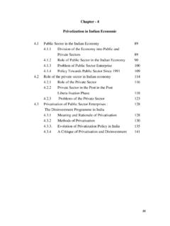
4 98 Figure Schematic Diagram of EXPERIMENTAL SETUP 99 Fig Photographic view of the EXPERIMENTAL SETUP List of components: 1. Engine 2. Dynamo meter 3. Air intake system 4. Fuel tank 5. Data acquisition system 6. Fly wheel 7. Frame 8. Load cell 9. Exhaust system 1 2 3 4 5 6 7 9 8 100 In the last part of EXPERIMENTAL work to scale back the thermal losses through the piston and to improve thermal potency of the engine the different piston crowns which are designed with completely different materials like cast iron, Copper and Brass, which are having different thermal conductivities. The experiments were conducted to seek out best crown material at the best air gap (identified in 2nd stage of experimentation) and with the best biodiesel at optimum mix concentration as a fuel.
5 EXPERIMENTAL SETUP The study was carried out in the IC engines laboratory on an EXPERIMENTAL engine test rig consisting of a single cylinder, water cooled, four stroke, vertical, stationary and constant speed diesel engine connected to eddy current type dynamometer for loading. It also contains the fuel supply system for supplying fuel, water cooling system for engine cooling, lubrication system and various sensors and instruments integrated with data acquisition system for online measurement of load, air and fuel flow rate, exhaust gas temperature, cooling water temperature. The SETUP enables the evaluation of thermal performance and emission constituents of the engine.
6 The thermal performance parameters include brake power, brake thermal efficiency, brake specific fuel consumption, and exhaust gas temperature. Thermocouples are provided at appropriate positions and are read by a digital temperature indicator with channel selector to select position. The SETUP also includes the necessary measuring instruments for the 101 measurement of smoke density and exhaust gas emissions. The exhaust emissions of the engine are analyzed by using an exhaust gas analyser. The constituents of the exhaust gas like CO, HC and NOx are measured with exhaust gas analyzer. The simple line diagram and photographic view of the EXPERIMENTAL SETUP are shown in Fig and respectively.
7 ENGINE The test engine used in the present work is a single cylinder, naturally aspirated, direct injection compression ignition engine of Kirloskar make. This diesel engine has a bore of 80mm and stroke of 110mm. The specification of the engine is shown appendix -A. The engine has a rated output of 5HP at a speed of 1500 rpm. The engine was coupled to an eddy current type dynamometer to apply the load on the engine with an electrical panel. The engine is mounted on a stationary frame with a suitable cooling system. The lubricating system is inbuilt in the engine. Reasons for choosing the Engine This engine can with stand higher pressures encountered and conjointly used extensively in agricultural and industrial sectors.
8 Thus this engine is chosen for carrying experiments. The necessary modifications on the piston needed for this work will simply be created. 102 Modification of test Engine In this EXPERIMENTAL work the test engine is modified into an Insulated engine with following necessary modifications. i) Diesel engine with air gap insulated piston. ii) Diesel engine with thermal barrier piston crown. Diesel engine with air gap insulated piston So as to reduce the heat transfer through the piston in this EXPERIMENTAL work an air gap insulated piston engine is developed that cut back the heat losses from the piston crown to the piston skirt.
9 This will increase the warmth within the chamber and heats the incoming charge of induction stroke. Thus with the air gap insulated piston the combustion and thermal efficiency are improved by reducing the heat losses. The insulated piston is to be just like the first piston with relation to dimensions and also the form of combustion chamber. The air gap insulated piston is shown within the 103 1 2 3 4 106 mm mm crown 2. Piston skirt 3. Gasket 4. Air gap Fig. Air gap insulated piston 104 Fig : Photographic view of thermal barrier piston crown List of components: 1. Piston crown 2. Piston skirt 3.
10 Piston ring groove 4. Screw 5. Piston pin seat Diesel engine with thermal barrier piston crown Piston is capable of holding heat from the combustion gases throughout the combustion and provides a similar to the incoming charge throughout the suction and compression strokes of consecutive cycle. This preheats the intake air, improves the 1 2 3 4 5 105 combustion potency and brake thermal potency [187]. So for this EXPERIMENTAL work three thermal barrier piston crowns are designed with whole completely different materials like cast iron, Copper alloy and Brass to scale back the heat losses from the piston crown to the piston skirt.