Transcription of Chapter 3 Robot Mechanisms - MIT OpenCourseWare
1 Introduction to Robotics, H. Harry Asada 1. Chapter 3. Robot Mechanisms A Robot is a machine capable of physical motion for interacting with the environment. Physical interactions include manipulation, locomotion, and any other tasks changing the state of the environment or the state of the Robot relative to the environment. A Robot has some form of Mechanisms for performing a class of tasks. A rich variety of Robot Mechanisms has been developed in the last few decades. In this Chapter , we will first overview various types of Mechanisms used for generating robotic motion, and introduce some taxonomy of mechanical structures before going into a more detailed analysis in the subsequent chapters.
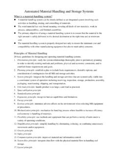
2 Joint Primitives and Serial Linkages A Robot mechanism is a multi-body system with the multiple bodies connected together. We begin by treating each body as rigid, ignoring elasticity and any deformations caused by large load conditions. Each rigid body involved in a Robot mechanism is called a link, and a combination of links is referred to as a linkage. In describing a linkage it is fundamental to represent how a pair of links is connected to each other. There are two types of primitive connections between a pair of links, as shown in Figure The first is a prismatic joint where the pair of links makes a translational displacement along a fixed axis.
3 In other words, one link slides on the other along a straight line. Therefore, it is also called a sliding joint. The second type of primitive joint is a revolute joint where a pair of links rotates about a fixed axis. This type of joint is often referred to as a hinge, articulated, or rotational (a) Prismatic joint (b) Revolute joint Figure Primitive joint types: (a) a prismatic joint and (b) a revolute joint Combining these two types of primitive joints, we can create many useful Mechanisms for Robot manipulation and locomotion.
4 These two types of primitive joints are simple to build and are well grounded in engineering design. Most of the robots that have been built are combinations of only these two types. Let us look at some examples. Robot Mechanisms analogous to coordinate systems One of the fundamental functional requirements for a robotic system is to locate its end- effecter, a hand, a leg, or any other part of the body performing a task, in three-dimensional space. If the kinematic structure of such a Robot mechanism is analogous to a coordinate system, 1.
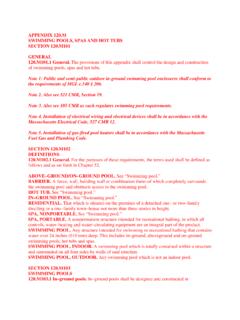
5 It is interesting to note that all biological creatures are made of revolute type joints; there are no sliding joints involved in their extremities. Department of Mechanical Engineering Massachusetts Institute of Technology Introduction to Robotics, H. Harry Asada 2. it may suffice this positioning requirement. Figures ~ 4 show three types of Robot arm structures corresponding to the Cartesian coordinate system, the cylindrical coordinate system, and the spherical coordinate system respectively. The Cartesian coordinate Robot shown in Figure has three prismatic joints, corresponding to three axes denoted x, y , and z.
6 The cylindrical Robot consists of one revolute joint and two prismatic joints, with r, and z representing the coordinates of the end-effecter. Likewise, the spherical Robot has two revolute joints denoted and and one prismatic joint denoted r. z2. y z1. Photo removed for copyright reasons. z 2. 1. Robot by Cincinnati Milacron. i3 x z0. Figure by MIT OCW. Figure Cartesian coordinate Robot Photo removed for copyright reasons. GMF Robotics model M-100. Figure by MIT OCW. Figure Cylindrical coordinate Robot Department of Mechanical Engineering Massachusetts Institute of Technology Introduction to Robotics, H.
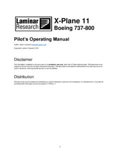
7 Harry Asada 3. Photo removed for copyright reasons. Figure by MIT OCW. Figure Spherical coordinate Robot . There are many other ways of locating an end-effecter in three-dimensional space. Figure ~ 7 show three other kinematic structures that allow the Robot to locate its end-effecter in three-dimensional space. Although these Mechanisms have no analogy with common coordinate systems, they are capable of locating the end-effecter in space, and have salient features desirable for specific tasks. The first one is a so-called SCALAR Robot consisting of two revolute joints and one prismatic joint.
8 This Robot structure is particularly desirable for assembly automation in manufacturing systems, having a wide workspace in the horizontal direction and an independent vertical axis appropriate for insertion of parts. z2 z1 z0. 1. Photo removed for copyright reasons. Robot by Adept. d3 2 1. 3. 0. Figure by MIT OCW. Figure SCALAR type Robot . Department of Mechanical Engineering Massachusetts Institute of Technology Introduction to Robotics, H. Harry Asada 4. The second type, called an articulated Robot or an elbow Robot , consists of all three revolute joints, like a human arm.
9 This type of Robot has a great degree of flexibility and versatility, being the most standard structure of Robot manipulators. The third kinematic structure, also consisting of three revolute joints, has a unique mass balancing structure. The counter balance at the elbow eliminates gravity load for all three joints, thus reducing toque requirements for the actuators. This structure has been used for the direct-drive robots having no gear reducer. Photo removed for copyright reasons. SCORBOT model ER 1X. Figure by MIT OCW.
10 Figure Articulated Robot Note that all the above Robot structures are made of serial connections of primitive joints. This class of kinematic structures, termed a serial linkage, constitutes the fundamental makeup of Robot Mechanisms . They have no kinematic constraint in each joint motion, each joint displacement is a generalized coordinate. This facilitates the analysis and control of the Robot mechanism. There are, however, different classes of Mechanisms used for Robot structures. Although more complex, they do provide some useful properties.