Transcription of CHAPTER 4 DESIGN AND CONSTRUCTION OF SEWAGE ... - …
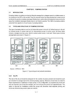
1 Part A: Engineering4 - 1 CHAPTER 4: DESIGN AND CONSTRUCTION OF SEWAGE PUMPING STATIONS AND SEWAGE PUMPING MAINSCHAPTER 4 DESIGN AND CONSTRUCTION OF SEWAGE PUMPING STATIONS AND SEWAGE PUMPING GENERAL CONSIDERATIONSP umping stations handle SEWAGE either as in-line for pumping the SEWAGE from a deeper sewer to a shallow sewer or for conveying to the STP or outfall. They are required where SEWAGE from low lying development areas is unable to be drained by gravity to existing sewerage infrastructure, and / or where development areas are too remote from available sewerage infrastructure to be linked by gravity means. DESIGN FlowRefer CHAPTER 3 of this Location and ConfigurationThe proper location of the pumping station requires a comprehensive study of the area to be served, to ensure that the entire area can be adequately drained.
2 Special consideration has to be given to undeveloped or developing areas and to probable future growth. The location of the pumping station will often be determined by the trend of future overall development of the area. The site should be aesthetically satisfactory. The pumping station has to be so located and constructed such that it will not get flooded at any time. The storm-water pumping stations have to be so located that water may be impounded without creating an undue amount of flood-damage, if the flow exceeds the pumping station capacity. The station should be easily accessible under all weather conditions. Pumping stations are typically located near the lowest point in a development. However, the siting and orientation of each pumping station shall be considered individually and based on the following criteria: Local topography as slope of the ground and above and below ground obstructions Proposed layout of the particular development and of future developments Proximity of proposed and/or existing sewerage infrastructure Size and type of the pumping station Access considerations for O&M needs including operators health and safety issues Visual impact, particularly the vent tube, odours, noise problems, etc.
3 , Availability of power , water, etc., Vulnerability of the site for inundation Compatibility to neighbouring residences by suitable these, the inundation is the key and can result in major environmental and health problems in case raw SEWAGE is flushed to the surface due to flooding of the wet well, or because of failure of Part A: Engineering4 - 2 CHAPTER 4: DESIGN AND CONSTRUCTION OF SEWAGE PUMPING STATIONS AND SEWAGE PUMPING MAINSthe system due to a partially/fully submerged switchboard. Inundation may also result in severe scouring around structures, particularly around the wet well, valve chamber, and possibly cause damage to the critical components such as the electrical switchboard. Accordingly, the designer shall establish the levels of the top of the wet well wall, top of valve chamber walls and top of the plinth supporting the electrical cubicle, so that those structures cannot be inundated by a flood of a 1 in 100-year recurrence interval.
4 Preferred method will be the formed ground level to be at the 1 in 100 -year flood level and building plinth and top of wet wells etc. shall be at m above. Ditch drain shall be mandatorily provided all around and if it is not possible to drain by gravity to the nearby natural drain. Drain pump sets shall be installed with 100% standby to pump out rain water and connected to the standby power . Rain-water harvesting shall not be provided in SEWAGE pumping stations to avoid ground water pollution by raw SEWAGE due to accidental spillage. Minimum number of wet wells shall be two, irrespective of the volume of SEWAGE to be pumped out and the structures shall be as far possible circular in plan to facilitate simpler and economical CONSTRUCTION , besides the possibility of removing accumulated grit from one of the wells at a time without interrupting the pumping Measures for Safety and Environment Protection 1.
5 Railing shall be provided around all manholes and openings where covers may be left open during operation and at other places, where there are differences in levels or where there is danger for people falling. 2. Guards shall be provided around all mechanical equipment, where the operator may come in contact with the belt-drives, gears, rotating shafts or other moving parts of the equipment. 3. Staircases shall be provided in preference to ladders, particularly for dry well access. Straight staircases shall be provided as against spiral or circular staircases or steps. The steps to be provided in the staircase shall be of the non-slippery type. 4. Telephone is an essential feature in a pump-house, as it will enable the operator to maintain contact with the main office.
6 In case of injury, fire or equipment-difficulty, the telephone will provide facility to obtain proper assistance as rapidly as possible. 5. Fire extinguishers, first-aid boxes and other safety devices shall be provided at all SPS. 6. A system of colours for pipes shall minimize the possibility of cross-connections. 7. To prevent leakages of explosive gases, the wet well should not be directly connected by any opening to the dry well superstructure. 8. All electrical equipment and wiring should be properly insulated and grounded and switches and controls should be of non-sparking type. All wiring and devices in hazardous areas should be explosion-proof. Part A: Engineering4 - 3 CHAPTER 4: DESIGN AND CONSTRUCTION OF SEWAGE PUMPING STATIONS AND SEWAGE PUMPING MAINS 9.
7 All pumping stations should have potable water supply, washroom and toilet facilities and precautions taken to prevent cross connections. 10. Hoisting equipment shall be provided for handling of equipment and materials, which cannot be readily lifted or removed by manual labour. Hence, in large pumping stations, gantries of adequate capacities shall be provided to lift the pumps, motors and large piping. 11. Fencing shall be provided around the pumping station to prevent trespassing. 12. The station should be landscaped to make it blend with the surroundings and to add to the aesthetic effect, particularly when residential areas are in the near vicinity of the station. 13. Adequate lighting is essential at the plinth and all locations of the pumping station and glares and shadows shall be avoided in the vicinity of machinery and floor DESIGN Suction Water LevelThe suction elevation should be preferably below the invert of the incoming sewer to facilitate air passage through the sewer in the reaches closer to the pump station.
8 A preferable drop of 50 cm to 100 cm below the invert of the incoming sewer is desirable to safeguard against problems of choking of sediments in sewers due to stagnations. DESIGN Discharge LevelThe water surface elevation in the receiving structure decides the static lift when compared to the suction level. However, friction losses and free-fall at receiving chamber are to be added to this to get at the DESIGN discharge level. As a rule, if needed this has to be increased such that the hydraulic grade line does not cut the longitudinal section of the ground level along the pumping main. This is achieved by raising the discharge elevation by means of a raised delivery line ending up in a goose-neck before dropping the flow into the receiving chamber such that the hydraulic grade line moves upwards in its terminal end and thus becomes free of the ground level.
9 The hydraulic grade line shall be at least 1 m above the highest ground level or the top most crown of the pumping Selection of power SourceThe power source will be the local electricity grid. A dedicated feeder from the nearby substation is recommended and in large pumping stations two such independent dedicated feeders from two different substations is to be considered. Drawing off a nearby power cable is permissible for small pumping stations handling less than 1 MLD of SCREEN AND GRIT GateIt is necessary to insert a penstock gate at the entry of the sewer into the wet well. The gate shall close by lowering the gate by either hand driven or motorized gear A: Engineering4 - 4 CHAPTER 4: DESIGN AND CONSTRUCTION OF SEWAGE PUMPING STATIONS AND SEWAGE PUMPING ScreensThese are needed to trap the floating matters like sachets, plastic milk packets, grocery bags, etc.
10 , which otherwise can lump in the impeller. The travelling mechanized endless screen is recommended so that man entry is totally avoided. For this purpose, it is necessary to restrict the width of flow to a rectangular profile in plan with the upstream length as at least three times the width and downstream length as at least two times the width. It is difficult to DESIGN and construct such a rectangular structure at deep depths. Hence, the recommended procedure is to construct the circular well first and fill up the arc sections with partitioned mass concrete to get at the rectangular passage. The DESIGN is invariably governed by equipment manufacturers who use the DWF and peak flows as the basis. In large pumping stations, it pays to have two successive screens: one coarse and the other fine, the idea being to have a back-up, in case one of them is in downtime.