Transcription of Chapter 4 FLOOR CONSTRUCTION
1 69 Chapter 4 FLOOR CONSTRUCTION Woodframe FLOOR systems and concrete slab-on-grade floors are discussed in this Chapter . Although cold-formed steel framing for FLOOR systems also is permitted by the IRC, it is not covered here; rather, the reader is referred to the AISI Standard for Cold-Formed Steel Framing Prescriptive Method for One- and Two-Family Dwellings (AISI, 2001) for guidance. Also permitted but not discussed here are pressure-treated wood FLOOR systems on ground; information on the use of these systems is provided in IRC Chapter 5. GENERAL FLOOR CONSTRUCTION REQUIREMENTS Woodframe FLOOR systems form a horizontal diaphragm at each level where they occur and transfer earthquake lateral loads to braced walls below that FLOOR level or directly to the foundation when the lowest FLOOR is supported on a foundation.
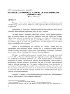
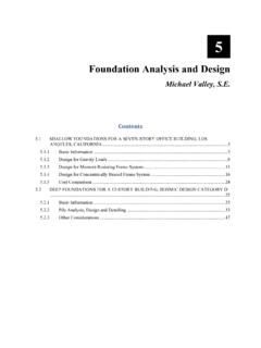
2 When a FLOOR supports walls above and is supported on walls below as shown in Figure 4-1, the lateral loads in the FLOOR system are based on the mass of the FLOOR itself and a portion of the mass of all the walls in the stories immediately above and below the FLOOR . (See Chapter 2 of this guide for a discussion of the complete load path.) Figure 4-1 An unblocked FLOOR diaphragm. FEMA 232, Homebuilders Guide 70 Concrete slab-on-grade floors typically are constructed with a concrete perimeter foundation and together these elements form the base of the building. Lateral forces from exterior and interior braced wall lines are transferred to a slab-on-grade via connections between the bottom plate of a braced wall and the slab.
3 In turn, the concrete slab and foundation transfer those forces directly to the ground as shown in Figure 4-2. (For more information on anchorage of braced walls to slab-on-grade CONSTRUCTION , see Chapter 3 of this guide.) Figure 4-2 Slab-on-grade and perimeter footing transfer loads into soil. WOODFRAME FLOOR SYSTEMS Woodframe floors typically consist of repetitive joists or trusses, at a prescribed spacing, sheathed with either boards or wood structural panels attached to the top surface. Finish materials such as gypsum board typically are applied to the bottom surface where it serves as the ceiling for a room below. Blocking between joists or trusses is used at the ends of the FLOOR joists or trusses (or a continuous band joist can be used at the ends) and where walls occur above or below.
4 FLOOR systems also include beams, girders, or headers where needed to support joists. Joists can be sawn lumber, end jointed lumber, or a variety of prefabricated (engineered) members. Examples of engineered lumber include wood I-joists, trusses, and solid rectangular structural composite members such as parallel strand lumber (PSL), laminated veneer lumber (LVL), and laminated strand lumber (LSL). Beams, girders, or headers and blocking also can be either sawn lumber or engineered lumber. Chapter 4, FLOOR CONSTRUCTION 71 The primary design consideration in choosing the minimum size and the maximum span and spacing of FLOOR joists, trusses, beams, girders, and headers is adequate support for dead and live vertical loads as prescribed by the code depending on the uses that a FLOOR must support.
5 Vertical deflection of a FLOOR is another design consideration that can limit the maximum span of FLOOR members. Tables in IRC Chapter 5 and similar tables in other documents such as those published by the American Forest and Paper Association (AF&PA) or engineered lumber manufacturers are available for use in selecting the proper combination of minimum size and maximum span and spacing of FLOOR framing members. CANTILEVERED FLOORS When FLOOR joists cantilever beyond a support, joist size and spacing are limited by prescriptive tables in IRC Chapter 5. IRC Table (1) addresses support of a roof and one story of wall for roof spans up to 40 feet and snow loads up to 70 psf.
6 IRC Table (2) addresses cantilever joists supporting an exterior balcony. When a FLOOR is supporting more than a roof and one story of wall, the maximum prescriptive cantilever distance is limited by the IRC to the depth of the joist. If longer cantilevers are desired, a registered design professional must design that portion of the FLOOR system . In Seismic Design Categories D1 and D2, when cantilevered FLOOR joists support braced wall panels in the story above, the cantilevered FLOOR is limited by several additional prescriptive requirements in IRC Chapter 3. This is because the braced wall above and braced wall below are offset out-of-plane. When a FLOOR cantilever supporting a braced wall does not meet the IRC limits, that portion of the house is defined as having an irregularity that prevents the use of prescriptive wall bracing where the irregularity occurs.
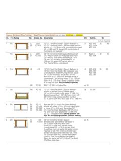
7 In such a case, engineering must be applied to resolve the out-of-plane offset of the braced walls located in the stories above and below that FLOOR . The maximum permitted cantilever of a second FLOOR supporting a braced wall and roof is illustrated in Figure 4-3. (Also see the discussion of load path in Chapter 2 of this guide.) Figure 4-3 Cantilevered FLOOR restrictions. FEMA 232, Homebuilders Guide 72 The specific limits and requirements in IRC Chapter 3 for cantilevered floors in SDCs D1 and D2 that support braced walls are not particularly difficult to meet and appear to omit addressing the uplift restraint that may be necessary at the back span support of cantilever joists.
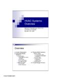
8 In SDCs D1 and D2, cantilever FLOOR joists supporting a braced wall panel may not extend more than four times the nominal depth of the joist when the following set of rules is met: Joists must be 2x10 nominal or larger at 16-inch maximum spacing. The back span of the cantilever joist must be at least twice the cantilever distance. Joists must be doubled at the ends of the braced wall panel above. A continuous rim joist is connected to the end of each cantilevered joist. If that rim joist is spliced along its length, the splice must be made with either: (a) a 16-gage strap having 6 16d common nails on each side of the splice or (b) by using wood blocking having the same size as the rim joist, installed between the cantilevered joists, and nailed to the rim with 8 16d common nails on each side of the splice.
9 The cantilever end of the joist is limited to supporting uniform loads from a roof and wall above and, if supporting a header above, the header span is limited to 8 feet. These rules are illustrated in the framing plan shown in Figure 4-4. What is not mentioned in this list of rules is the need for connections to resist uplift at the back-span (interior) end of a cantilever joist as noted in Figure 4-4. In IRC Table (1) for cantilever joists supporting a roof and wall, the uplift is determined using a back-span distance that is three times the cantilever distance (3:1). Because the minimum back span specified in the IRC Chapter 3 (see Item 2 above) is only twice the cantilever distance (2:1), the uplift values in IRC Table (1) would need to be increased by a factor of just to address the gravity loads.
10 When the downward earthquake overturning load from the ends of a braced wall panel supported by cantilever joists are considered in addition to gravity loads, the uplift load at the back-span end of the joist obviously will increase. Therefore, depending on the actual back-span-to-cantilever-length ratio, the back-span end of the double cantilever joists supporting the ends of a braced wall may need to provide uplift restraint as much as twice than that listed in IRC Table (1). However, because the magnitude of the uplift load at the back-span end of a cantilevered joist reduces as the back-span length increases, it is possible that a cantilever joist that is continuous over its interior support will result in zero uplift at the back-span end.