Transcription of CHAPTER 4 MATERIALS TESTING PROGRAM METHODS AND ASSUMPTIONS
1 4-1 CHAPTER 4 MATERIALS TESTING PROGRAM METHODS AND ASSUMPTIONSThis CHAPTER provides information to use when conducting or reviewing TESTING results that will be usedin geotechnical and stability analyses for a waste containment facility in Ohio. It also addresses selectingappropriate test results for MATERIALS and interfaces that will be used for design or construction. At a minimum, TESTING of in situ soil MATERIALS must occur during the subsurface investigation whenpreparing to design a waste containment facility. TESTING of soil MATERIALS that will be used for structuralfill, recompacted soil layers, and other engineered components can be conducted during the subsurfaceinvestigation (recommended) or as conformance TESTING before construction. TESTING of the interfaceshear strengths of geosynthetics and the internal shear strengths of geosynthetic clay liners (GCL), islikely to occur as conformance TESTING .
2 This is due to frequent changes in geosynthetic MATERIALS on themarket and the time between design and construction. However, designers may want to evaluate theirdesigns against appropriate test results for typical MATERIALS that are available. This will allow thedesigner to evaluate the likelihood that appropriate MATERIALS will be available when is expected that the appropriate ASTM test METHODS or other applicable standards will be followedwhenever TESTING of MATERIALS is being performed. When using approved test METHODS , ensure the testingapparatuses and the specimens are prepared and used so that the test results are appropriatelyconservative in representing the field conditions in which the soils and geosynthetics will be used. Common tests used during geotechnical investigations addressed in this CHAPTER are:For soils; !
3 Standard Test Method for Direct Shear Test of Soils Under Consolidated Drained Conditions(ASTM D 3080),!Standard Test Method for Unconsolidated-Undrained Triaxial Compression Test on Cohesive Soils(ASTM D 2850),!Standard Test Method for Unconfined Compressive Strength of Cohesive Soil (ASTM D 2166),!Standard Test Method for Consolidated-Undrained Triaxial Compression Test for Cohesive Soils(ASTM D 4767), and!Standard Test Method for One-Dimensional Consolidation Properties of Soils (ASTM D 2435). CHAPTER 4 - MATERIALS TESTING PROGRAM METHODS and Assumptions4-2 For interface TESTING ;!Standard Test Method for Determining the Coefficient of Soil and Geosynthetic or Geosyntheticand Geosynthetic Friction by the Direct Shear Method (ASTM D 5321), and!Standard Test Method for Determining the Internal and Interface Shear Resistance of GeosyntheticClay Liner by the Direct Shear Method (ASTM D 6243).
4 GENERAL CRITERIA FOR MODELING SITECONDITIONS WHEN PREPARING SAMPLESAND RUNNING TESTSIn 1974, Ladd stated, The results of researchhave shown that major variations in strengthcan be caused by sample disturbance, strengthanisotropy, and strain-rate effects. None ofthese effects is explicitly included in presentdesign practice. The reason the presentmethods generally work is that the variationsfrequently tend to be self-compensating. It istherefore quite possible for the resulting designto be either unsafe or overly conservative,particularly in view of the large scatter oftenfound in triaxial test data. Additional researchsince then has continued to confirm thesefindings ( , Jamiolkowski, et al, 1985).Failure planes propagate through the materialsand interfaces that exhibit the weakest shearstrength at any given loading. The materialsand interfaces that are the weakest are likely tochange as the normal load and displacementchanges.
5 As a result, failure planes maypropagate through several different interfacesand MATERIALS . At many waste containmentfacilities, a large array of MATERIALS andcombinations of MATERIALS often exist undervarying normal loads that need to be evaluatedfor shear strength. Furthermore, wastecontainment facilities can have widely varyingsite conditions that may affect the applicabilityand/or validity of TESTING results, and the siteconditions are likely to change over time. Because of these variables, it is extremelyimportant to ensure that samples of soil andconstruction MATERIALS are prepared and tested so that they conservatively represent the expected worst-case field conditions for each facility-specific design. Factors Affecting the Validity and Accuracy of Soil Shear Strength TestingThe commonly used unconfined compression tests andunconsolidated-undrained triaxial compression tests tend toproduce values of undrained shear strengths that exceedfield values because of the triaxial compression stresscondition and the high strain rate used (60%/hr).
6 However,sample disturbance, on the other hand, tends to cause lowervalues of undrained shear strength provided that drying ofthe sample is avoided. These effects may compensate eachother and yield a reasonable average design shear strength. However, the method is highly empirical and thesecompensating factors are not controlled or controllable, butin practice, the disturbance effects can be greater than thetesting effects and thus the resulting undrained shearstrengths are often conservative. The situation is furtherconfused by the tendency for sample disturbance effects toincrease with depth and to obscure shear strength variationsin the profile. Sample disturbance typically underestimatesthe undrained shear strength of a sample from 20 to 50%. Stress-strain anisotropy can cause differences between theundrained shear strength obtained by different tests to varyby a factor of to For triaxial compression tests, eachlog cycle decrease in strain rate is typically accompanied bya 10 to 15% decrease in undrained shear strength.
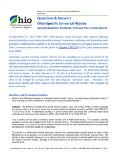
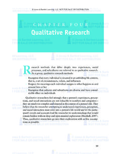
7 Forhighly plastic, creep susceptible clays, triaxial compressionstrength obtained from consolidated samples failed at anaxial strain rate of 60%/hr (typical for UU triaxial andUnconfined Compression tests) can be to times theshear strength obtained at (typical for CU triaxialtests w/pore water pressure measurement) (Quoted andadapted from Ladd, 1974). The variability discussed byLadd is largely independent of the triaxial compression testconducted and thus is inherent in the variability of soilmaterial properties and the difficulties experienced duringsampling. As a result, variations in values of undrainedshear strength are still found in TESTING today (Stark, 2002). CHAPTER 4 - MATERIALS TESTING PROGRAM METHODS and Assumptions4-3 Figure 4-1 Example of a compound peak shear strengthenvelope for a multi-layered engineered component of awaste containment is important to model failure surface propagationthrough a composite system at varying normalloads.
8 To do this, the individual failure envelopesof each material and interface in the compositesystem can be plotted on one shear stress stress graph. The weakest compoundenvelope (see Figure 4-1) can then be determinedand used for calculating or verifying the stability ofthe composite system (see Conformance Testingstarting on page 4-15 for more details).At some facilities, the shear strength of a materialcannot be ascertained through laboratory TESTING . Using empirical relationships then becomes theonly alternative. On the rare occasion that this isnecessary, the theoretical or empirical correlationthat produces the weakest reasonable estimate ofthe shear strength should be used. For example,when using correlations between liquid limit andshear strength, the highest liquid limit measuredthat is representative of the soil unit should be usedto estimate the shear strength, instead of averaging a number of liquid limits from several samples.
9 In situ foundation MATERIALS and project-specificmaterials must be tested for internal and interfaceshear strengths over the entire range of normalstresses that will be encountered by the materialsand interfaces for a given design. The range ofnormal stresses that need to be evaluated can beextensive, varying from low values at theperimeter of a facility to much higher values underthe deepest areas of a facility. For cover systems,this range includes the low normal stresses causedby the cap MATERIALS and any additional stressesthat may be induced by surface water diversionbenches, roads, or other structures constructedabove the cover system, and equipment. Shear strength tests are performed by shearing different specimens of the same material or interface atthree to five different normal loads to develop the failure envelope. For each test, at least one specimenshould be sheared at a load that is as near as possible, or preferably below, the lowest expected normalstress that will be experienced by the material or interface in the field.
10 One specimen should be shearedat a load that is at least 110 percent of the maximum normal stress expected to be experienced by thematerial or interface in the field. The remaining specimens should be sheared at normal loads welldistributed between the low and high loads. If a reasonable expectation exists that at a future timethe waste containment facility may be expanded in amanner that will increase the normal stresses associatedwith the facility, then the responsible party shouldensure that MATERIALS and interfaces selected forconstruction are tested at the higher normal loads. Otherwise, future expansion may be precluded becauseit will be unknown if the existing MATERIALS can maintainstability under the higher normal loads, and thematerials that were used may no longer bemanufactured or otherwise available for 4 - MATERIALS TESTING PROGRAM METHODS and Assumptions4-4 Care must be taken to prevent damage or changes to undisturbed samples that would invalidate testresults.