Transcription of Chapter 4 Shear and Moment In Beams - ncyu.edu.tw
1 Mechanics of MaterialsChapter 4 Shear and Moment In Beams Introduction The termbeamrefers to a slender bar that carries transverse loading; that is, the applied force are perpendicular to the bar. In a beam , the internal force system consist of a Shear force and a bending momentacting on the cross section of the bar. The Shear force and the bending Moment usually vary continuously along the length of the beam . The internal forces give rise to twokinds of stresses on a transverse section of a beam : (1) normal stressthat is caused by bending momentand (2) Shear stressdue to the Shear force.
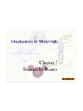
2 Knowing thedistribution of the Shear force and the bending Moment in a beam is essential for the computation of stresses and deformations. Which will be investigated in subsequent (a) Statically determinate and Loads Beams are classified according to their supports. A simply supported beam ,shown in Fig. (a). The pin supportprevents displacement of the end of the Beams , but not its rotation. The term roller supportrefers to a pin connection that is free to move parallel to the axis of the beam ; this type of support suppresses only the transverse displacement.
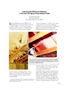
3 Figure Statically determinate Beams A cantilever beamis built into a rigid support at one end, with the other end being free,as shown in (b). The built-in supportpreventsdisplacementsas well asrotations of the end of the beam . An overhanging beam , illustrated in (c), is supported by a pinand a roller support, with one or both ends of the beam extending beyond thesupports. The three types of beamsare statically determinatebecause the support reactions can be found from the equilibrium equations. ()gg()gg(c) 2003 Brooks/Cole Publishing / Thomson Learning (c) 2003 Brooks/Cole Publishing / Thomson Learning Aconcentrated load, such as Pin Fig.
4 (a). In contrast a distributed loadis applied over a finite area. If the distributed load acts on a very narrow area, the load may be approximated by a line load. The intensity wof this loading is expressed as force per unit length (lb/ft, N/m, etc.) The load distribution may be uniform, as shown in (b), orit may vary with distancealong the beam , as in (c). The weight of the beamis an example of distributed loading, but its magnitude is usuallysmallcompared to the loads applied to the beam .()gg()gg(c) 2003 Brooks/Cole Publishing / Thomson Learning (c) 2003 Brooks/Cole Publishing / Thomson Learning Figure Statically indeterminate Beams Figure shows other types of Beams .
5 These Beams are oversupportedin the sense that each beam has at least one morereaction than is necessary for support. Such Beams arestatically indeterminate; the presence of these redundant supportsrequires the use of additional equationsobtained by considering the deformation of the beam . The analysis of statically indeterminate Beams will be discussed in Chapter 7. Shear - Moment Equations and Shear - Moment Diagrams The determination of the internal force system acting at agivensection of a beam : draw a free-body diagramthat expose these forces and then compute the forces using equilibrium equations.
6 The goal of the beam analysis determine the Shear force Vand the bending Moment Matevery cross section of the beam . To derive the expressions for Vand Min terms of the distance xmeasured along the beam . By plotting these expressions to scale, obtain theshear force and bending Moment diagramsfor the beam . The Shear force and bending Moment diagrams are convenient visual references to the internal forces in a beam ; in particular, they identify the maximum valuesof Vand Sign conventions()k/lblihi/h i()k/lblihi/h iFigure Sign conventions for external loads; Shear force, and bending Procedure for determining Shear force and bending Moment diagrams Compute the support reactionsfrom the free-body diagram (FBD) of the entire beam .
7 Divide the beam into segmentso that the loading within each segment is continuous. Thus, the end-pointsof the segments are discontinuities of loading, including concentrated loadsand couples. Perform the following steps for each segment of the beam : Introduce an imaginary cutting planewithin the segment, located at a distance x from the left end of the beam , that cuts the beam into two parts. Draw a FBD for the part of the beam lying either to the left or to the right of the cutting plane, whichever is more convenient.
8 At the cut section, show V and M acting in their positive directions. Determine the expressions for Vand Mfrom the equilibrium equationsobtainable from the FBD. These expressions, which are usually functions of x, are the Shear force and bending Moment equations for the segment. Plot the expressions for V and M for the segment. It is visually desirable to draw the V-diagrambelowthe FBD of the entire beam , and then draw the M-diagrambelowtheV-diagram. The bending Moment and Shear force diagrams of the beam are composites of the Vand Mdiagrams of the segments.
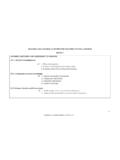
9 These diagrams are usually discontinuous, or have discontinuous slopes. At the end-pointsof the segments due to discontinuities in simply supported beam in Fig. (a) carries two concentrated loads. (1) Derive the expressions for the Shear force and the bending Moment for each segment of the beam . (2) Sketch the Shear force and bending Moment diagrams. Neglect the weight of the beam . Note that the support reactions at Aand Dhave been computed and are shown in Fig. (a). SolutionPart 1 The determination of the expressions for Vand Mfor each of the three beam segments (AB,BC, and CD) is explained below.
10 Segment AB (0 x 2 m) Fy=0 + 18-V= 0V= +18 kNAnswer ME= 0 + 4- 18x+ M= 0M= +18x kN m AnswerSegment AB (2 x 5 m) Fy=0 + 18-14-V= 0V= +18-14 = +4 kNAnswer ME= 0 + 4- 18x + 14(x-2) + M= 0M= +18x-14(x-2) = 4x+28 kN m AnswerSegment CD (5 m x 7 m) Fy=0 + 18-14 28-V= 0V= +18-14-28 = -24 kNAnswer MG= 0 + 4- 18x+ 14(x-2)+28(x-5)+M= 0M= +18x-14(x-2) (x-5) = -24x+168 kN m AnswerPart 2 The V-diagram reveals that the largestshear forcein the beam is -24 kN : segment CD The M-diagram reveals that the maximumbending momentis +48 kN m : the 28-kN load at C.