Transcription of Chapter 5 Parabolic Trough Technology - EDGE
1 Advanced CSP Teaching Materials Chapter 5. Parabolic Trough Technology Authors Matthias G nther1. Michael Joemann1. Simon Csambor1. Reviewers Amenallah Guizani2. Dirk Kr ger3. Tobisas Hirsch4. 1. Institute for Electrical Engineering, Rational Energy Conversion, University of Kassel, Wilhelmsh her Allee 73, 34121 Kassel 2. Centre des Recherches et Technologies de L'Energie , BP 95 Hamam lif 2050, Tunisia 3. German Aerospace Center (DLR) -Solar Research, Linder H he 51147 Cologne, Germany 4. German Aerospace Center (DLR)-Solar Research, Pfaffenwaldring 38-40, 70569 Stuttgart, Germany 1. Table of Contents 1 Introduction ..7. 2 History of Parabolic Trough power plant Technology ..9. 3 Power plant components .. 13. Parabolic Trough collector .. 14. Collector geometry .. 14. Mirror material .. 22. Bearing structure .. 27. Sun Tracking System .. 40. 44. Receiver 45. Receiver efficiency .. 51. Heat transfer 55. Heat transfer fluid in indirect steam generation power plants.
2 55. Direct steam generation .. 58. Solar field .. 64. Solar field 64. Solar field 65. Solar field 68. 4 Power plant integration .. 71. Solar field size, storage, solar multiple .. 71. Base load, intermediate load and peak load plant configuration .. 73. Hybridisation .. 75. 5 Efficiency of Parabolic Trough power 80. Solar-to-electric efficiency .. 80. Solar field efficiency .. 81. Power block losses .. 87. Parasitic energy uses .. 88. Reference List .. 89. Annex .. 94. 1 Proof that a parabola has a focal point .. 94. 2 Proof that parabolas with the same rim angle are geometrically similar .. 96. 3 Derivation of the relation between rim angle, focal length and aperture width .. 98. 4 Derivation of the Parabolic Trough surface area .. 98. Questions .. 100. 2. Answers .. 102. Exercises .. 103. Solutions .. 106. 3. Nomenclature Symbol Meaning Unit Latin letters a aperture width m A surface area m . active receiver surface area m.
3 Collector aperture area m . receiver aperture area m . aperture area m . total receiver surface area m . b insulation thickness m C concentration ratio - geometrical concentration ratio - d receiver diameter m f focal length of Parabolic Trough m direct irradiance on the collector aperture W/m2. irradiance in the Sun image W/m2. irradiance on receiver W/m2. h heat transfer coefficient IAM incidence angle modifier - l collector length m rated electrical power W. total energy input W. useable energy output W. power that is absorbed by the receiver glass tube W. conductive heat transfer W. convective heat transfer W. convective heat loss of the absorber tube W. convective heat loss of the receiver glass tube W. optical receiver loss W. thermal receiver loss W/m heat transfer through radiation W. power loss due to radiant emittance of the absorber W. power loss due to radiant emittance of the receiver glass W. tube power loss due to reflection on the absorber W.
4 Power loss due to reflection on the receiver glass tube W. useable energy flow W. distance between absorber tube and mirror rim m s tracking angle , rad S parabola length ( Trough cross-section) m SM solar multiple - ambient temperature C, K. high temperature level in a thermodynamic cycle C, K. surface temperature of heat transfer element C, K. low temperature level in a thermodynamic cycle C, K. T temperature C, K. 4. Greek letters absorptance - sun beam angle ', rad weighted average absorptance for black-body radiation at - temperature T. spectral absorptance - azimuth angle . solar azimuth angle . dispersion angle ', rad weighted average emissivity for black-body radiation at the - temperature T. emissivity (in specific spectral range) - efficiency - power block efficiency - optical solar field efficiency at incidence angle - solar field efficiency - maximum thermal-to-mechanical conversion efficiency - incidence angle.
5 Solar zenith angle . wavelength M. thermal conductivity W/(mK). collector length use factor - intercept variance factor - optical parameter variance factor - reflectivity - Stefan-Boltzmann constant W/(m ). transmittance - rim angle . hour angle . Acronyms ASE Archimede Solar Energy BOP Balance of plant CSP Concentrating Solar Power DISS Direct Solar Steam DLR German Aerospace Center DNI Direct Normal Irradiation DSG Direct steam generation HCE Heat Collection Element HTE Heat Transfer Element HTF Heat Transfer Fluid IAM Incidence Angle Modifier NREL National Renewable Energy Laboratory PCM Phase Change Material PSA Plataforma Solar de Almer a SCA Solar Collector Assembly SEGS Solar Energy Generating System SM Solar Multiple 5. Summary In this section we will get to know the currently most frequent form of large scale CSP plants: Parabolic Trough power plants. We will learn about their history and their current status. We will understand their structure and how their components work.
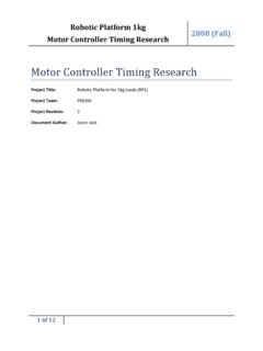
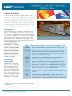
6 Important design parameters will be explained. At the end, the efficiency of the generation of electricity with Parabolic Trough power plants will be specified. Key questions Which is currently the dominating CSP Technology ? What are the milestones in the history of Parabolic Trough power plants? What are the main components of a Parabolic Trough power plant and how do they work? What are central parameters in the design of a Parabolic Trough power plant? How efficient are Parabolic Trough power plants? 6. 1 Introduction Parabolic Trough power plants use Parabolic Trough collectors to concentrate the direct solar radiation onto a tubular receiver. Large collector fields supply the thermal energy, which is used to drive a steam turbine, which, on its part, drives the electric generator. Figure 1: Parabolic power plants in southern Spain (Andasol 1 and 2, in the back ground on the right side the prepared construction ground for Andasol 3, source: Solar Millenium).
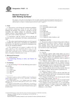
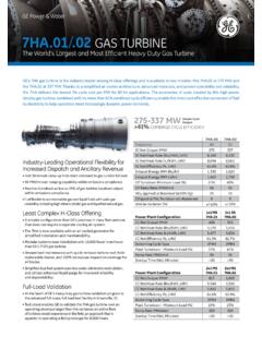
7 Parabolic Trough power plants constitute the biggest share of the installed concentrating solar power Technology . Distinguishing between Parabolic Trough power plants, Fresnel power plants, solar tower power plants and dish/Stirling systems, the Parabolic Trough power plants provide over 90% of the capacity of concentrating solar power plant Technology that is in operation or in construction in September 2010. Among the planned additional capacity (at the same date) more than 50% are constituted by Parabolic Trough power plants. The following figure shows the absolute numbers and the shares of the four Technology types among the plants in operation, in construction, in the planning stage, and, finally, the sum of all of them. 5. 5. Photon, Sept. 2010 ( German journal for solar Technology ). 7. Figure 2: Percentage of different solar thermal power technologies 8. 2 History of Parabolic Trough power plant Technology John Ericsson constructed in 1880 the first known Parabolic Trough collector.
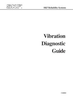
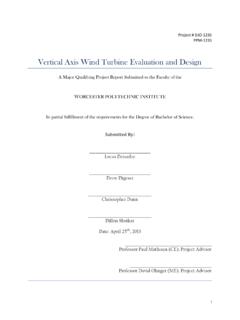
8 He used it to power a hot air engine. In 1907, the Germans Wilhelm Meier and Adolf Remshardt obtained the first patent of Parabolic Trough Technology . The purpose was the generation of In 1913, the English F. Shuman and the American Boys constructed a 45 kW pumping plant for irrigation in Meadi, Egypt, which used the energy supplied by Trough collectors. The pumps were driven by steam motors, which received the steam from the Parabolic troughs. The constructors used Parabolic Trough collectors with a length of 62m and an aperture width of 4m. The total aperture area was 1,200 m .7 The system was able to pump 27,000 litres of water per minute. 8. Despite the success of the plant, it was shut down in 1915 due to the onset of World War I and also due to lower fuel prices, which made more rentable the application of combustion technologies. Figure 3: Parabolic Trough collector application in Egypt built in 1913 (source: Ragheb 2011).
9 The interest in the Parabolic Trough Technology did not rise again until 1977, when the US Department of Energy as well as the German Federal Ministry of Research and Technology began to fund the development of several process heat machines and water pump systems with Parabolic Trough collectors. Higher fossil fuel prices encouraged the governments to take new measures. Results of these measures were, for instance, the following: - Between 1977 and 1982, the company Acurex installed Parabolic Trough demonstration systems with a total aperture area of almost 10,000 m in the USA for process heat applications. - The first modern line-focusing solar power plant was a 150 kWe facility that was built in 1979. in - Nine member states of the International Energy Agency participated in the project of building demonstration facilities with a rated power of 500 kW at the Plataforma Solar de Almeria, which was put into operation in 1981.
10 - The first private financed process heat machine with 5580 m Parabolic Trough collectors was successfully put into operation in 1983 in Arizona for thermal heating of electrolyte tanks in a copper processing company. 10 These Trough systems developed for industrial process heat application were capable of generating temperatures higher than 260 C. In 1983, Southern California Edison (SCE) signed an agreement with Luz International Limited to purchase power from the first two commercial solar thermal power plants that should be constructed in the Mojave Dessert in California. These power plants, called Solar Electric Generating System 6. See Geyer et al. 2002. 7. See Nava et al. 1996. 8. See Ragheb 2011. 9. See Winter et al. 1991, p. 216. 10. See Geyer et al. 2002. 9. (SEGS) I and II, started operation in the years 1985 and 1986. Later, Luz signed a number of standard offer contracts with SCE that led to the development of the SEGS III to SEGS IX plants.