Transcription of Chapter 5 - Schemes of directional control valves - ISO ...
1 Chapter 5: ISO Schemes of directional control valves Page 1 Hafner-Pneumatik Kr mer KG, Stammheimerstra e 10, D-70806 Kornwestheim, Germany, Phone: 0049-7154-178589-0, E-Mail: web : Schemes of directional valves The description of directional valves is standardized by DIN ISO 121. IMPORTANT! The ISO symbols display only the function of the valves . They do not give any further information about the design, flow, orifice size, etc. Basics of the ISO symbols: Each position the valve can take is represented by a square. The number of squares tells you the number of positions the valve can take. The air pathways are represented by lines. The direction of the airflow is represented by an arrow. In case air flows in both directions there is a double arrow. Closed ports are displayed as a T. The ports carry numbers. The numbers are only shown in the square with the basic position of the valve.
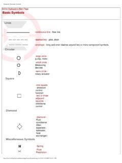
2 The type of actuation is also symbolized. The ISO-symbol contains information concerning the stability of the positions and the reset. directional valves number of ports and positions The directional valves are described by the numbers of ports in the main valve (excluding pilot ports) and the number of positions the valve can take, [number of ports] / [number of positons] for example: 2 squares = 2 positons 3 ports Number of positions Number of ports In this case we speak of a 3/2 way valve (spoken: three two way valve). Each position of the valve is displayed in a square. The basic position is symbolized by the numbers of the ports. Chapter 5: ISO Schemes of directional control valves Page 2 Hafner-Pneumatik Kr mer KG, Stammheimerstra e 10, D-70806 Kornwestheim, Germany, Phone: 0049-7154-178589-0, E-Mail: web : On the right hand side you can see the basic position of a normally closed 3/2-way valve.
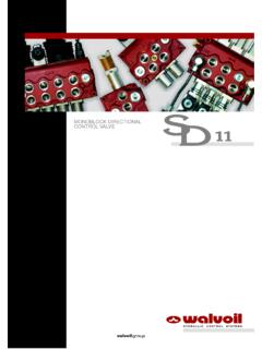
3 Port 1 = pressure supply is closed (blue). Port 2 = working, in basic position connected to port 3 = exhaust (red). Basic position or normal position drawn in green. The second square displays the actuated position of the valve. Valve has been actuated (actuation elements not shown here). Port 1 is connected to working port 2 (blue). Exhaust port 3 is closed (black). Actuated positon drawn in green. Symbols of the most common valves 2/2-way valve Normally closed Normally open 3/2-way valve Normally closed Normally open Chapter 5: ISO Schemes of directional control valves Page 3 Hafner-Pneumatik Kr mer KG, Stammheimerstra e 10, D-70806 Kornwestheim, Germany, Phone: 0049-7154-178589-0, E-Mail: web : 4/2-way valve 5/2-way valve 4/3-way valve Center closed 5/3-way valve Center closed Symbols of actuation elements and resets Apart from the squares showing the valve's function, the symbols for its actuation elements and elements to reset/return it are shown on the left, respectively right side of them.
4 Mechanically actuated, Actuation by stem With spring reset Mechanically actuated, Actuation by roller lever With air spring reset Mechanically actuated, Actuation by roller lever with idle return With combined (mechanical) spring and air spring reset Chapter 5: ISO Schemes of directional control valves Page 4 Hafner-Pneumatik Kr mer KG, Stammheimerstra e 10, D-70806 Kornwestheim, Germany, Phone: 0049-7154-178589-0, E-Mail: web : Manually actuated, Actuation with a push-button Manually actuated, Actuation by a lever Manually actuated, Actuation by a lever, indexed, 2 positions Actuated by foot / foot valve Pneumatically actuated Electrically actuated, Direct actuated valve Electrically actuated, Solenoid pilot valve Manual override Pneumatically actuated, Differential piston, dominating side Pneumatically actuated, Differential piston.
5 Chapter 5: ISO Schemes of directional control valves Page 5 Hafner-Pneumatik Kr mer KG, Stammheimerstra e 10, D-70806 Kornwestheim, Germany, Phone: 0049-7154-178589-0, E-Mail: web : Numbering of ports All the ports in the valve are counted through. The numbers indicate the function of the port. The numbers always appear on the square for the valve's basic/normal position. In case we talk about a valve with 2 stable positions, the numbers are shown for the implicit standard position . Basic position = normal position is the position the valve is in without actuation. Pressure supply 1 P Working port(s) 2, 4, (6) A, B, C Exhaust(s) 3, 5, 7 R, S, T Pilot ports(s) 10, 12, 14 X, Y, Z Examples: The following lever- and pneumatically actuated valves allow airflow in both directions (double arrows). Actuation : manually (by a lever) 2 positions, both stable, indexed Number of pneumatic ports: 5 Thus: 5 ports, 2 positions = 5/2-way valve Manually actuated, 5/2-way valve, indexed Type : HVR 520 701 Chapter 5: ISO Schemes of directional control valves Page 6 Hafner-Pneumatik Kr mer KG, Stammheimerstra e 10, D-70806 Kornwestheim, Germany, Phone: 0049-7154-178589-0, E-Mail: web : Actuation : pneumatically (with air) 2 positions, one stable (with spring reset) Number of pneumatic ports: 5 plus pilot port 14 Thus: 5 ports, 2 positions = 5/2-way valve Pneumatically actuated 5/2-way valve, single pilot, mechanical spring reset Type : P 511 701 Actuation : electrically (solenoid-pilot) including manual override.
6 3 positions, one stable (spring centered) Number of pneumatic ports: 5 Thus: 5 ports, 3 positions = 5/3-way valve Solenoid-pilot 5/3-way valve, 2 springs center the spool. Center position closed. Type : MH 531 701 Chapter 5: ISO Schemes of directional control valves Page 7 Hafner-Pneumatik Kr mer KG, Stammheimerstra e 10, D-70806 Kornwestheim, Germany, Phone: 0049-7154-178589-0, E-Mail: web : General information on circuits Looking at the following circuits you can see potential ways for using different types of directional valves . 2/2-way valves 2/2-way valves are for opening and closing. They block the medium or let it pass. 2/2-way valves can be either normally closed or normally open. In the scheme below two 2/2-way solenoid valves (S1 and S2) are used to control a cylinder with spring return (single acting) C1.
7 Without actuation both solenoid valves are closed. In order to move the piston rod to the outer position (right) S2 has to be actuated. Compressed air is flowing from the source through S2 into the cylinder. In order to move the piston rod to the opposite position S2 needs to be de-energized and S1 has to be actuated. In case none of the valves are actuated, the piston rod stays in last position. (The symbol at the bottom displays an FRL-unit (filter, regulator, lubricator). The functions of cylinders as well as of air-preparation units will be discussed in a later Chapter .) Chapter 5: ISO Schemes of directional control valves Page 8 Hafner-Pneumatik Kr mer KG, Stammheimerstra e 10, D-70806 Kornwestheim, Germany, Phone: 0049-7154-178589-0, E-Mail: web : 3/2-way valves 3/2-way valves are mostly used to control single acting actuators.
8 They can be normally closed or normally open. In the scheme below you can see two applications. 1. An electrically actuated 3/2-way valve (S1) controls the single acting cylinder (C1). When the valve is actuated, air flows from 1 to 2; the piston rod of the cylinder is moving to outer position. When the valve is de-energized, it switches back to normal position and the mechanic spring in the cylinder drives the piston rod back. 2. The double acting cylinder (C2) is controlled by a 5/2-way valve (Y1). Valve Y1 is controlled by an electrically actuated, normally closed 3/2-way valve (S2). Valve S2 is actuated (air flows from port 1 to port 2). The air actuates valve Y1. It switches and air flows from port 1 to port 4; the piston rod of cylinder C2 moves to the outer position. As soon as valve S2 is de-energized, air exhausts from port 2 to 3. Valve Y1 switches back into normal position because of the built-in mechanic spring.
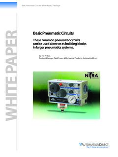
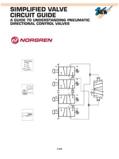
9 Compressed air in valve Y1 flows from 1 to 2 and the cylinder's exhaust from 4 to 5 as the piston rod moves back in. Chapter 5: ISO Schemes of directional control valves Page 9 Hafner-Pneumatik Kr mer KG, Stammheimerstra e 10, D-70806 Kornwestheim, Germany, Phone: 0049-7154-178589-0, E-Mail: web : 4/2-way and 5/2-way valves 4/2-way and 5/2-way, as well as 4/3-way and 5/3-way valves are usually used to control double acting actuators. In the example below a manually actuated valve (S1 or S2) controls a double acting cylinder (C1 or C2). Additionally, in order to control the speed of the cylinder, flow control silencers are in use. The major difference between the 4-way and the 5-way valve is that the 4-way valve offers only one exhaust port. Therefore the speed of the piston rod moving in or out cannot be controlled independently as the two chambers of cylinder C1 are exhausted through the same exhaust port 3 of valve S1.
10 As for the 5/2-way valve (S2), the two chambers on cylinder (C2) are exhausted through separate exhaust ports (5 and 3). This offers the possibility to regulate the speed of the piston rod independently.