Transcription of Chapter 5 – Sectional Views - University of New Mexico
1 Chapter 5 Sectional Views There are a number of different types of Sectional Views that can be drawn. A. few of the more common ones are: full sections, half sections, broken sections, rotated or revolved sections, removed sections, offset sections, and assembly sections. These Sectional Views are very useful when there is geometry on the interior of a part that is difficult to understand from looking at typical orthographic Views . They are also very useful in dimensioning the drawing. It is considered poor practice to dimension to a hidden line and Sectional Views allow us to dimension the interior of a part without dimensioning to hidden lines. All of the various types of Sectional Views can be drawn with autocad .
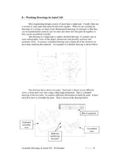
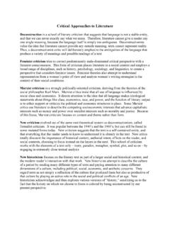
2 A. typical example is shown below. Here we are using a full section to dimension much of the object. Without this Sectional view, we would be forced to dimension to hidden lines. Create Orthographic Drawing You start this tutorial by drawing the top and front third angle Views of the object shown on the right. The process is exactly like the drawings we have done in the past so it will not be covered here. Be sure to dimension the Views using the techniques we used in a previous assignment. The required layers are listed below and shown in the figure at the top of the next page.. Center centerlines Cut cutting plane Dim dimensions Fold folding lines Hatch cross hatching Sectional Views in autocad R Greenlee Page |1.
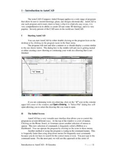
3 Hide hidden lines Obj object lines Proj projection lines The exterior features of the object are dimensioned in the front view but the interior details are not. Dimensioning the interior features would require dimensioning to hidden lines which is poor practiced. The problem is eliminated by creating a Sectional view which shows the interior details. Once this view has been created, you can dimension the interior details in the Sectional view to complete the drawing. Copy View to Be Cross Sectioned Start the process by copying the front view (third angle projection) of the object. We will transform the copied front view into the Sectional view. Before you start the COPY process, 2.
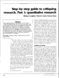
4 Make sure you have drawn the hidden and center lines. Turn off the dimension layer because you do not want to copy the dimensions along with the front view. The 4. center and hidden lines must be visible because they must be copied to the Sectional view we are creating. 3. 1 Front View Copy of Front View COPY. Select objects: W {create a rectangular window around the front view to select the entire view}. Specify first corner: {1 - Click at a location to the left of and below the entire view}. Specify opposite corner: {2 - Click at a location to the right of and above the entire view}. Select objects: {Press Enter to end the selection process}. Specify base point {3 - Click on a point on the front view.}
5 This is where you will grab the copy}. Specify second point {4 -Drag the view to where you want it. If ORTHO is on the view can only be moved horizontally or vertically}. After copying the front view, turn dimension layer back on so the dimensions will show in the front view. Sectional Views in autocad R Greenlee Page |2. Modify Copy to Create Sectional View We can now alter the copied front view to create a half Sectional view. We are creating a half Sectional view because the object is symmetrical about the vertical axis which makes it ideal for a half section. The half section will show the left side of the object as a normal orthographic view and the right side as a Sectional view.
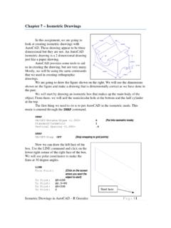
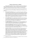
6 First, use the TRIM command to eliminate the interior lines that are not needed. Use the centerline, hidden lines, and selected object lines as the cutting planes to trim away some of the interior lines. When you have finished, your drawing should look like the one on the right Next, switch the current layer to the object layer and draw over the hidden lines to complete the outline of the Sectional view. We continue to work on this view by deleting all of the hidden lines in the view because we do not show hidden lines in Sectional Views . This is easily done by turning off all of the layers except for the hidden lines then using the ERASE command to delete all of the hidden lines belonging to this view.
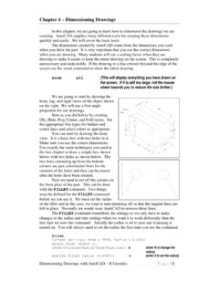
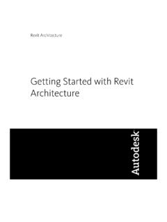
7 When you have finished, turn the layers back on. You should have a drawing similar to the one on the right. Sectional Views in autocad R Greenlee Page |3. Cross Hatching Sectional View Now we can cross hatch the cut surfaces. This is a very simple process. Switch the current layer to the Hatch layer and enter: HATCH. This command brings up the ribbon shown below. 1. Select ANSI 31. 2. Select Pick Points autocad can draw many different types of cross hatching. The different types Click Here can be used to indicate the material from to fill with which the part is made. It is especially useful cross hatching in assembly Sectional Views where different parts are made from different materials.
8 We have only one type of material so we will just use a simple 45 cross hatch. Click on the ANSI31 icon. This is the cross hatch scheme we want to use. Next, click on the Pick Points icon on the extreme left of the ribbon. After you have clicked on the Pick Points icon, click in the area of the drawing where you want the cross hatching to appear. autocad can automatically cross hatch any closed area. When you have finished, the entire drawing should look like the one on the right. All that remains is to draw the cutting plane on the top view. Drawing the Cutting Plane Lines Switch to the Cut layer to draw the cutting plane. The lines in this layer should be a little wider than the object lines and the linetype should be Phantom.
9 A line width of mm seems to work well for many drawings. Start by drawing lines from the center of the part to a point beyond the right side, and a line from the center to a point below the outer circle in the top view. The exact length of the lines is not important. Turn OSNAP and ORTHO on then draw the lines with the mouse. Note that the dimensions in the top Sectional Views in autocad R Greenlee Page |4. view had to be relocated to accommodate the cutting plane. The results are shown at the right. Cutting Plane Arrowheads Now we can add the arrowhead to the end of the cutting plane. Surprisingly enough, autocad does not provide an automatic facility for doing this.
10 We will use the multileader facility to draw the arrowheads. These arrowheads should be a little larger than the ones used for dimensioning and we will make them twice as large. Start by entering the command: mleaderstyle This will produce the dialog box shown on the right. This dialog box is used to define leader styles. We will use it to define a new style so that we can produce the arrowheads we need. Click on the New button to create a new multileader style. This opens the dialog box shown on the right. Enter Cutting for the new style name and start with Standard which is the current multileader style. Be sure to mark the Annotative box at the bottom of the dialog box.