Transcription of Chapter 5 Stresses In Beams - ncyu.edu.tw
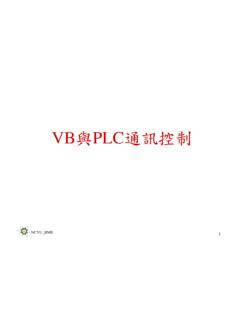
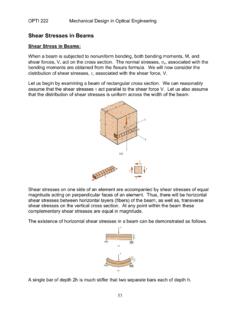
1 Mechanics of MaterialsChapter 5 Stresses In Introduction In previous chapters, the Stresses in bars caused by axial loading and torsion. Here consider the third fundamental loading : bending. Make certain simplifying assumptions. the resulting equations have served well in the design of straight, elastic Bending Stressa. Simplifying assumptions The Stresses caused by the bending moment are known asbending stress,or flexure relationshipbetween these Stresses and the bending moment is called the flexure formula. In deriving the flexure formula, make the following assumptions: The beam has an axial plane of symmetry, which we take to be the xy-plane(see Fig. ). Figure Symmetrical beam withloadslying in the plane of symmetry.
2 The applied loads(such as F1,F2and F3in ) lie in the plane of the symmetryand are perpendicular tothe axis of the beam (thex-axis).The axis of the beam bends but does not stretch( the axis lies some where in the plane of symmetry; its location will be determined later). Plane sections of the beam remain plane(do not warp ) and perpendicular tothe deformed axis of the beam. Change in the cross-sectional dimensionsof the beam are negligible. Figure Symmetrical beam Because the shear stressescaused by the vertical shear forcewill distort (warp)an originally plane section, we are limiting our discussion here to the deformations caused by the bending momentalone. the deformations due to the vertical shear forceare negligiblein the slender Beams compared to the deformations caused by bending.
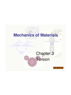
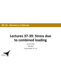
3 The above assumptions lead us to the following conclusion: Each cross section of the beam rotates as a rigid entity about aline called the neutral axis of the cross section. The neutral axispasses through the axis of the beamand is perpendicular tothe plane of symmetry, as shown in Fig. The xz-plane that contains the neutral axesofall the cross sections is known as the neutral surfaceof the beam. Figure Deformation of an infinitesimal beam Compatibility The neutral surface becomes curved upon deformation, as indicated in The longitudinal fibers lying on the neutral surfaceare undeformed, whereas the fibersabove the surface are compressed and the fibersbeloware The fiber form are arc a' b'of radius ( -y) , subtended by the angle d , its deformed length is The original length of this fiber is The normal strain of the fiber () dyba =''.
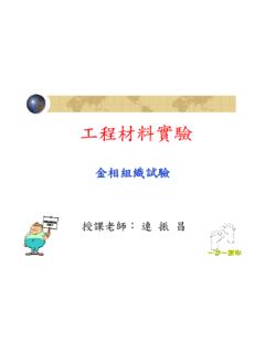
4 Ddxab==() ydddyababba = = ='' Assuming that the stress is less thanthe proportional limit of the material we can obtain the normal stress in the fiber ab from Hook s law: ( )Equation ( ) shown that the normal stress of a longitudinal fiber isproportional to the distance y of the fiber from the neutral == The negative signindicates that positive bending momentcauses compressive stress whenyis positive(fiber above the neutral surface) and tensile stress when yis negative (fiber below the neutral surface).c. Equilibrium Figure shows the normal force acting on the infinitesimal area dA of the cross section is dP = dA. Substituting = - (E/ )y, (a)Where yis the distance of dAfrom the neutral axis (NA).
5 The resultant of the normal stress distribution over the cross section must be equal to the bending moment M acting about the neutral axis (z-axis). Figure Calculating the resultant of the Normal stress acting on the cross section. Resultant is a couple Equal to the internal bending moment of = In other work, where the integral is taken over the entire cross-sectional area A = AMydp the resultant axial forceand the resultant bending momentabout the y-axis must be zero; that is,andThese three equilibriumequations are developed in detail below. =AdP0 =AzdP0 Resultant Axial Force Must Vanish The condition for zero axial force is = =AAydAEdp0 Resultant Moment About y-Axis Must VanishThis condition is Because E / 0, this equation can be satisfied only if (b)The integral in Eq.
6 (b) is the first moment of the cross-sectional area about the neutral axis. It can be zero only if the neutral axis passes throughcentroid C of the cross-sectional area. =AydA0(c)The integral in Eq.(b)is the product of inertia of the cross-sectional area. = =AAzydAEzdP0 Resultant Moment About the Neutral Axis Must Equal MEquating the resultant moment about the z-axis to MRecognizing that is the moment of inertia of the cross-sectional area about the neutral axis ( the z-axis),we obtain the moment curvature relationship( )A convenient form of this equation is ( ) == AAMdAyEydp2 =AIdAy2 EIM=EIM= 1 = AMydp The maximum valueof bending stresswithout regard to its sign is given by( )wherec is the distance from the neutral axis to the outermost point of the cross Flexure formula; section modulus Substituting the expression for 1/ from Eq.
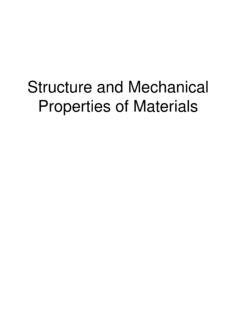
7 ( ) into Eq. ( ), we get the flexure formula:( )Note that a positive bending moment M causes negative (compressive) stress above the neutral axisand positive ( tensile) stress below the neutral axisIMy = []IcMmaxmax= Equation ( ) is frequently written in the form( )where S = I / cis called thesection modulusof the beam. The dimension of Sis [L3], so that its units are , mm3, and so on. The formulas for the section moduli of common cross sections are given in Fig. []SMmaxmax= Figure Section moduliof simple cross sectional Section moduli of simple cross sectional shapes. The section moduli of standard structural shapes are listed in various handbooks; an abbreviated list is given in Appendix B.
8 2003Bk/ClPblihi/ThL i 2003Bk/ClPblihi/ThL i e. Procedures for determining bending Stresses Stress at a Given Point Use the method of sections to determine the bending moment Mat the cross section containing the given point. Determine the location of the neutral axis. Compute the moment of inertia I of the cross- sectional areaabout the neutral axis. ( If the beam is standard structural shape, its cross- sectional properties are listed in Appendix B. P501) Determine the y-coordinate of the given point. Note thaty is positive if the point lies above the neutral axisand negative if it lies below the neutral axis. Compute the bending stress from = -My / correct sign are used for Mandy, the stress will also have the correct sign (tension positive compression negative).
9 Maximum Bending Stress: SymmetricCross SectionIf the neutral axis is an axis of symmetric of the cross section, the maximum tensile and compression bending Stresses are equal in magnitudeand occur at the section ofthe largest bending moment. The following procedure is recommended for determining the maximum bending stress in a prismatic beam: Draw the bending moment diagramby one of the methods described in Chapter 4. Identify the bending moment Mmaxthat has the largest magnitude (disregard the sign) Compute the moment of inertia I of the cross- sectional areaabout the neutral axis. ( If the beam is a standard structural shape, its cross- sectional properties are listed in Appendix B.) Calculate the maximum bending stress from max= [Mmax]c / I, where c is the distance from the neutral axis to the top or bottom of the cross section.
10 MaximumTensile and Compressive Bending Stresses : Unsymmetrical Cross SectionIf the neutral axis is not an axis of symmetry of the cross section, the maximum tensile and compressive bending Stresses may occur at different sections. Draw the bending moment diagram. Identify the largest positive and negative bending moments. Determine the location of the neutral axisand record the distances ctopand cbotfrom the neutral axis to the top and bottom of the cross section. Compute the moment of inertia I of the cross section about the neutral axis. Calculate the bending stressesat the top and bottom of the cross sectionwhere the largest positive bending momentoccurs from = -My / the top of the cross section, where y = ctop,we obtain top= -Mctop/ the bottom of the cross section, we have y = - cbot, so that bot= Mcbop/ I.