Transcription of Chapter 6 Deflection of Beams - ncyu.edu.tw
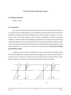
1 Mechanics of MaterialsChapter 6 Deflection of Introduction Because the design of Beams is frequently governed by rigidity rather than strength. For example, building codes specifylimits on deflectionsas well as stresses . Excessive deflectionof a beam not only is visually disturbing but also may cause damage to other parts of the building. For this reason, building codes limit the maximum Deflection of a beam to about1/360 thof its spans. A number of analytical methods are available for determining the deflections of Beams . Their common basis is the differential equationthat relatesthe deflectiontothe bending moment. The solution of this equation is complicated because the bending momentis usually adiscontinuousfunction, so that the equations must be integrated in apiecewise such methodsin this text: Method of double integrationThe primary advantage ofthe double- integration method is that it produces the equation for the Deflection everywhere along the Beams .
2 Moment-area methodThe moment- area method is a semigraphical procedurethat utilizes the properties of the area under the bending moment diagram. It is the quickest wayto compute the Deflection at a specific locationif the bending moment diagram has a simple shape. Themethod of superposition, in which the applied loading is represented as a series of simple loadsfor which Deflection formulas are available. Then the desired Deflection is computed by adding the contributions of the component loads(principle of superposition). Double- Integration Method Figure (a) illustrates the bending deformation of a beam , the displacements and slopesare very smallif the stresses arebelowthe elastic limit. The deformed axis of the beam is called its elastic curve. Derive the differential equationfor the elastic curveand describe a methodfor its solution.
3 Figure (a) Deformation of a (a) Deformation of a equation of the elastic curve As shown, the vertical Deflection of A, denoted by v, is considered to bepositive if directed in the positive direction of the y-axis-that is,upwardin Fig . (a). Because the axisof the beam lies on the neutral surface, its length does not change. Therefore, the distance , measured along the elastic curve, is also x. It followsthat the horizontal Deflection of Ais negligibleprovided the slope of the elastic curve remains small. Consider next the deformation of an infinitesimal segment ABof the beam axis, as shown in Fig. (b). The elastic curve A B of the segment has the same length dxas the undeformed segment. If we let vbe the Deflection of A, then the Deflection of Bis v+dv,withdvbeing the infinitesimal change in the Deflection segment are denoted by and +d.
4 From the geometry of the figure,( ) From Fig. (b), dx= d (a)Figure (b) Deformation of a differential element of beam axis =sindxdvThe approximation is justified because is small. From Fig. (b), dx= d (a)where is the radius of curvatureof the deformed segment. Rewriting Eq. (a) as 1/ = d /dxand substituting from Eq. ( ), ( )When deriving the flexure formula in Art. , we obtained the moment-curvature relationship( repeated)where Mis the bending moment acting on the segment, Eis the modulus of elasticity of the beam material, and Irepresents the modulus of inertia of the cross-sectional area about the neutral (centroidal) axis. 221dxvd= EIM= 1 Substitution of Eq.( ) into Eq.( )yields( )which the differential equation of the elastic curve. The product EI, called the flexural rigidityof the beam , is usually constantalong the beam .
5 It is convenient to write Eq. ( )in the form EI v = M( )Where the prime denotes differentiation with respect to x ; that is, dv/dx= v , d2 v/dx2 = v , and so on. EIMdxvd= integration of the differential equationIfEIis constantand Mis a known function of x, integration of Eq. ( ) yields( )A second integration gives ( )where C1and C2are constants of integrationto be determined from the prescribed constraints(for example, the boundary conditions) on the deformation of the beam . Because Eq. ( ) gives the Deflection vas a function of x, it is called the equation of the elastic curve. +=1'CMdxEIv21 CxCMdxdxEIv++= In Eq. ( ), the term gives the shape of the elastic curve. The position of the curve is determined by the constants of integration : C1represents a rigid-body rotation about the originand C2is a rigid-body displacementin the , the computation of the constants is equivalent to adjusting the position of the elastic curve so that it fits properly on the supports.
6 If the bending moment of flexural rigidity is not a smooth function of x, a separate differential equationmust be written for each beam segment between the discontinuities. This means that if there are nsuch segments, twointegrations will produce 2nconstants of integration(two per segment). There are also 2nequations available for finding the constants. Mdxdx The elastic curve must not contain gaps or kinds. In other words, theslopesand deflectionsmust becontinuousat the junctions where the segments meet. Because there are n-1junctions between the nsegments, these continuity conditionsgive us 2(n-1)equations. Twoadditional equationsare provided by theboundary conditionsimposed by the supports, so that there are a total of 2 (n-1)+2 = 2nequations. for double integration The following procedure assumes that EIis constantin each segment of the beam : Sketch the elastic curve of the beam , taking into account the boundary conditionszero displacement at pin supportsas well as zero displacement and zero slope at built-in (cantilever ) supports.
7 Use the method of sections to determine the bending moment Mat an arbitrary distance x from the origin. Always show Macting in the positive directionon the free-body diagram. If the loading has discontinuities, a separate expression for Mmust be obtained for each segment between the discontinuities. By integration the expressions for Mtwice, obtain an expression for EI in each segment. Do not forget to include the constants of integration. Evaluate the constants of integrationfrom the boundary integration and the continuity integrationon slope and deflectionbetween only the magnitude of the Deflection , called the displacement, is required. We denote the displacement by ; that is, . =Sample cantilever beam ABof length Lshown in Fig.(a) carries a uniformly distributed load of intensityw0, which includes the weight of the beam .
8 (1) Derive the equation of the elastic curve. (2) Compute the maximum displacement if the beam is a W12 35 section using L= 8 ft, w0= 400 lb/ft, and E= 29 106 psi. Solution Patr1 The dashed line in Fig. (a) represents the elastic curve of the beam . The bending moment acting at the distance xfrom the left end can be obtained from the free-body diagram in Fig. (b) (note that Vand Mare shown acting in their positive directions):22200xwxxwM = =Substituting the expression for Minto the differential equation EI = M, 220"xwEI = Successive integrations yield (a) (b)The constants C1and C2are obtained from the boundary conditions at the built-in end B, which are : 1. x=L= 0 (support prevent rotation at B) . Substituting = 0 and x = Linto Eq. (a), 2. x=L= 0 (support prevent Deflection at B).
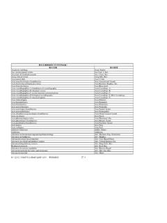
9 With = 0 and x = L, Eq.(b) becomes 214024 CxCxwEI++ = 6301 LwC=230406240 CLLwLw+ +=8402 LwC=130'6 CxwEI+ = If we substitute C1and C2into Eq. (b), the equation of the elastic curve isAnswerpart 2 From Table in Appendix B (P521), the properties of a W12 35 shape are I = 285 S = (section modulus). From the result of part 1. the maximum displacement of the beam is (converting feet to inches)Answer8624403040 LwxLwxwEI += ()43403424 LxLxwEI + = ()()()(). ==== The magnitude of the maximum bending moment, which occurs at B, is Mmax= w0L2/2. Therefore. the maximum bending stress iswhich close to the proportional limit of 35000 psi(P503) for structural steel. The maximum displacement is very small compared to the length of the beam even when the material is stressed to its proportional limit. ()()() === Sample Problem simple supported beam ABCin Fig.
10 (a) carries a distributed load of maximum intensity w0 over its span of length L. Determine the maximum displacement of the bending moment and the elastic ( the dashed line in Fig. (a)) are symmetric about the midspan. Therefore, we will analyze only the left halfof the beam (segmentAB). Because of the symmetry, the reactions areRA= RC= w0 bending moment in ABcan be obtained from the free-body diagram in Fig. (b), yielding ()320200431234xxLLwxLxwxLwM = =()3204312"xxLLwEI = 142202312'CxxLLwEL+ = (a)(b)2153205212 CxCxxLLwEI++ = The two constantcan be evaluated from the following two conditionson the the elastic curve of segment AB:1. |x=0=0 (no Deflection at Adue to the simple support). C2= 0 2. |x=L/2= 0 ( due to symmetry, the slope at midspan is zero), 14401683120 CLLLw+ =1925301 LwC=2153205212 CxCxxLLwEI++ = 142202312'CxxLLwEL+ = The equation of the elastic curve for segment AB: By symmetry, the maximum displacement occurs at midspan.