Transcription of CHAPTER 6 HEAT TRANSFER APPLICATIONS - …
1 CHAPTER 6 heat TRANSFER APPLICATIONS The principles of heat TRANSFER are widely used in food processing in many items of equipment. It seems appropriate to discuss these under the various APPLICATIONS that are commonly encountered in nearly every food factory. heat EXCHANGERS In a heat exchanger, heat energy is transferred from one body or fluid stream to another. In the design of heat exchange equipment, heat TRANSFER equations are applied to calculate this TRANSFER of energy so as to carry it out efficiently and under controlled conditions. The equipment goes under many names, such as boilers, pasteurizers, jacketed pans, freezers, air heaters, cookers, ovens and so on. The range is too great to list completely. heat exchangers are found widely scattered throughout the food process industry. Continuous-flow heat Exchangers It is very often convenient to use heat exchangers in which one or both of the materials that are exchanging heat are fluids, flowing continuously through the equipment and acquiring or giving up heat in passing.
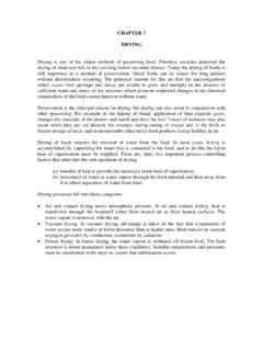
2 One of the fluids is usually passed through pipes or tubes, and the other fluid stream is passed round or across these. At any point in the equipment, the local temperature differences and the heat TRANSFER coefficients control the rate of heat exchange. The fluids can flow in the same direction through the equipment, this is called parallel flow; they can flow in opposite directions, called counter flow; they can flow at right angles to each other, called cross flow. Various combinations of these directions of flow can occur in different parts of the exchanger. Most actual heat exchangers of this type have a mixed flow pattern, but it is often possible to treat them from the point of view of the predominant flow pattern. Examples of these heat exchangers are illustrated in Figure In parallel flow, at the entry to the heat exchanger, there is the maximum temperature difference between the coldest and the hottest stream, but at the exit the two streams can only approach each other's temperature.
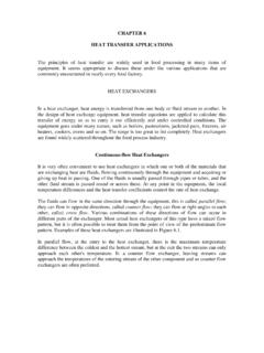
3 In a counter flow exchanger, leaving streams can approach the temperatures of the entering stream of the other component and so counter flow exchangers are often preferred. Figure heat exchangers Applying the basic overall heat TRANSFER equation for the heat TRANSFER in the heat exchanger: q= UA T uncertainty at once arises as to the value to be chosen for T, even knowing the temperatures in the entering and leaving streams. Consider a heat exchanger in which one fluid is effectively at a constant temperature, Tb as illustrated in Fig. (d), where time t is on the x-axis and temperature T on the y-axis. Constant temperature in one component can result either from a very high flow rate of this component compared with the other component, or from the component being a vapour such as steam or ammonia condensing at a high rate, or from a boiling liquid.
4 The heat TRANSFER coefficients are assumed to be independent of temperature. The rate of mass flow of the fluid that is changing temperature is G kgs-1, its specific heat is cp J kg-1oC -1. Over a small length of path of area dA, the mean temperature of the fluid is T and the temperature drop is dT over time dt. The constant temperature fluid has a temperature Tb. The overall heat TRANSFER coefficient is U J m-2s-1 oC-1 Therefore the heat balance over the short length is: cpGdT = U(T - Tb)dA Therefore (U / cpG) dA = dT /(T T b) If this is integrated over the length of the tube in which the area changes from A = 0 to A = A, and T changes from T1 to T2, we have: (U/cpG) A = ln[(T1 T b)/(T2 - Tb)] where ln = loge = ln( T1/ T2) in which T1 = (T1 T b) and T2 = (T2 T b) Therefore cpG = UA/ ln ( T1/ T2) From the overall equation, the total heat transferred per unit time is given by q = UA Tm where Tm is the mean temperature difference.
5 But the total heat transferred per unit is also: q = cpG (T1 T 2) so q = UA Tm = cpG (T1 T 2) = [UA/ ln ( T1/ T2)] x (T1 T 2) but (T1 T 2) can be written (T1 T b) - (T2 - Tb) so (T1 T 2 ) = ( T1 - T2) therefore UA Tm = UA( T1 - T2) / ln ( T1/ T2) ( ) so that Tm = ( T1 - T2) / ln( T1/ T2) ( ) where Tm is called the log mean temperature difference. In other words, the rate of heat TRANSFER can be calculated using the heat TRANSFER coefficient, the total area, and the log mean temperature difference. This same result can be shown to hold for parallel flow and counter flow heat exchangers in which both fluids change their temperatures. The analysis of cross-flow heat exchangers is not so simple, but for these also the use of the log mean temperature difference gives a good approximation to the actual conditions if one stream does not change very much in temperature.
6 EXAMPLE Cooling of milk in a pipe heat exchanger Milk is flowing into a pipe cooler and passes through a tube of internal diameter at a rate of kgs-1. Its initial temperature is 49oC and it is wished to cool it to 18oC using a stirred bath of constant 10oC water round the pipe. What length of pipe would be required? Assume an overall coefficient of heat TRANSFER from the bath to the milk of 900Jm-2s-1 oC-1, and that the specific heat of milk is 3890 Jkg-1oC-1. Now q = cpG (T1 T 2) = 3890 x x (49 - 18) = 48,240Js-1 Also q = UA Tm Tm = [(49 - 10) - (18 10)] / ln[(49 -10)1(18 - 10)] = Therefore 48,240 = 900 x A x A = but A = DL where L is the length of pipe of diameter D Now D = L = ( x ) = This can be extended to the situation where there are two fluids flowing, one the cooled fluid and the other the heated fluid.
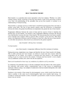
7 Working from the mass flow rates (kgs-1) and the specific heats of the two fluids, the terminal temperatures can normally be calculated and these can then be used to determine Tm and so, from the heat TRANSFER coefficients, the necessary heat - TRANSFER surface. EXAMPLE Water chilling in a counter flow heat exchanger In a counter flow heat exchanger, water is being chilled by sodium chloride brine. If the rate of flow of the brine is kgs-1 and that of the water is kgs-1, estimate the temperature to which the water is cooled if the brine enters at 8oC and leaves at 10C, and if the water enters the exchanger at 32oC. If the area of the heat - TRANSFER surface of this exchanger is 55 m2, what is the overall heat - TRANSFER coefficient? Take the specific heats to be and the brine and the water respectively. With heat exchangers a small sketch is often helpful. In this counter flow exchanger, Figure , the brine flows along the top (temperatures T1 and T2), and water along the bottom (temperatures T1 and T2 ).
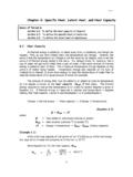
8 Figure Diagrammatic heat exchanger Three temperatures are known and the fourth T 2 can be found from the heat balance: Brine: entering T1 = -8oC, leaving T2 =10oC Water: entering T2 = 32oC, leaving T1 heat gain in brine = heat loss in water cpG (T1 T 2) = cpG (T1 T 2 ) x [10 - (-8)] = x x (32 T2 ) (32 T1 ) = 25 Therefore T1 = 7oC. And so for counter flow (T1 T1 ) = T1 (T2 T2 ) = T2 T1 = [-8 - 7] = 15oC and T2 = [10 - 32] = 22oC. Therefore Tm = (22 - 15)/ln(22/15) = 7 = For the heat exchanger, from the heat balance, heat loss from brine = heat gain to water q = heat passed across heat TRANSFER surface = UA Tm Therefore x x 18 = U x 55 x U = Overall heat TRANSFER coefficient = 110 Jm-2s-1oC-1 Parallel flow can be worked out similarly making appropriate adjustments. In some cases, heat exchanger problems cannot be solved so easily; for example, if the heat TRANSFER coefficients have to be calculated from the basic equations of heat TRANSFER which depend on flow rates and temperatures of the fluids, and the temperatures themselves depend on the heat TRANSFER coefficients.
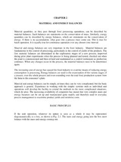
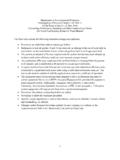
9 The easiest way to proceed then is to make sensible estimates and to go through the calculations. If the final results are coherent, then the estimates were reasonable. If not, then make better estimates, on the basis of the results, and go through a new set of calculations; and if necessary repeat again until consistent results are obtained. For those with multiple heat exchangers to design, computer programmes are available. Jacketed Pans In a jacketed pan, the liquid to be heated is contained in a vessel, which may also be provided with an agitator to keep the liquid on the move across the heat - TRANSFER surface, as shown in Fig. (a). Figure heat exchange equipment The source of heat is commonly steam condensing in the vessel jacket. Practical considerations are: 1. There is the minimum of air with the steam in the jacket. 2. The steam is not superheated, as part of the surface must then be used as a de-superheater over which low gas heat TRANSFER coefficients apply rather than high condensing coefficients.
10 3. Steam trapping to remove condensate and air is adequate. The action of the agitator and its ability to keep the fluid moved across the heat TRANSFER surface are important. Some overall heat TRANSFER coefficients are shown in Table Save for boiling water, which agitates itself, mechanical agitation is assumed. Where there is no agitation, coefficients may be halved. TABLE SOME OVERALL heat TRANSFER COEFFICIENTS IN JACKETED PANS Condensing Heated Pan heat TRANSFER coefficients fluid fluid material Jm-2s-1oC-1 Steam Thin liquid Cast-iron 1800 Steam Thick liquid Cast-iron 900 Steam Paste Stainless steel 300 Steam Water, boiling Copper 1800 EXAMPLE Steam required to heat pea soup in jacketed pan Estimate the steam requirement as you start to heat 50kg of pea soup in a jacketed pan, if the initial temperature of the soup is 18oC and the steam used is at 100kPa gauge.