Transcription of Chapter 6. Tolerance Analysis
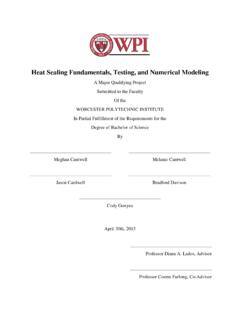
1 39 Chapter 6. Tolerance Analysis When locators have displacements (caused by manufacturing or positioning error), the workpiece will be displaced, and errors will occur on machining surfaces (Figure ). With the given locator tolerances, can we predict the amount of error it causes for machining surfaces? Can we determine the locator tolerances based on the machining surface Tolerance specifications? These questions are to be answered in this Chapter . T L2 L1 L3 P1 P2 WCS GCS Figure Tolerance Analysis Tolerance Analysis in CAFDV studies the relationship between locator tolerances and machining surface tolerances within a single setup.
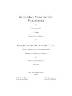
2 The scope does not include studies on fixture assembly and multi-setup Tolerance stack up. In CAFDV, Tolerance Analysis has two tasks machining surface accuracy check and locator Tolerance assignment. The former calculates the machining surface accuracy with given locator tolerances, and the latter finds the optimal locator tolerances based on 40machining surface Tolerance . The figure below best illustrates the relationship between accuracy check and Tolerance assignment. Locator Displacements Machining Surface Displacement accuracy check Tolerance assignment Figure Accuracy Check and Tolerance Assignment In order for computer implementation, machining surfaces are represented by sample points (Section ).
3 Tolerances are then defined based on surface sample points (section ). Then accuracy check and Tolerance assignment are discussed (Section and ). Machining Surface Sample Points For computer implementation, machining surfaces must be represented with finite points. These points are sampled from the surface contour, since the largest surface deviation always occurs on the contour. And the surface accuracy is defined by finding the largest deviation among its contour points. Figure Surface Sample Points 41 For surface deviation calculation, sample points are taken at each vertex on surface, and more points are taken from a curve to increase precision (Figure ).
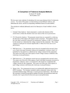
4 The deviations of contour points are calculated based on the workpiece location deviation, and the machining surface error is then calculated by its Tolerance type. Definition of Surface Deviation and Accuracy For a given Tolerance type, the machining surface deviation can be calculated based on its sample point deviations. The calculation follows the standards set in ANSI (ANSI, 1995). Figure shows the target surface and the deviated surface, along with their sample points. deviated surface contour sample points (p) target surface contour point deviation ( p) surface normal (n) p1 pi pnn1 ninnp1 pi pn Figure Surface Deviation Machining Surface Accuracy For a given Tolerance type, the surface accuracy is the envelop for all possible deviations, which is equivalent to the maximal deviation (the worst case).
5 For a qualified surface, its accuracy must fall within the specified Tolerance . The calculation for each type of machining accuracy is listed in the following sections. Surface Profile and Line Profile Deviation For surface and line profile, they are defined as double the maximum sample point deviation. They can be calculated as (Figure ): {}nnn2n1 p p pmax2devL = ( ) where, iinin p p = is the sample point deviation along surface normal direction Parallelism, Perpendicularity and Angularity Deviation For parallelism, perpendicularity and angularity, their surface deviations are calculated as the difference between maximum and minimum sample point deviations (Figure ).
6 {}{}nnn2n1nnn2n1 p p pmin p p pmaxdevLL = ( ) Position Deviation The deviation calculation for position type is a little different from other types. The sample points are derived from the cylinder axis instead of from the surface contour. It is defined to be double the maximum deviation from the target axis (Figure ): {}nnn2n1 d d dmax2devL = ( ) piaxis pi diaxis deviated Figure Position Deviation Other Types of Deviations Other types of deviation, such as plane surface flatness, cylindrical surface run-out, symmetry, are not considered in this work.
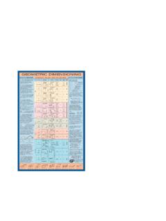
7 The reason is that they are not affected by locator displacements. Machining Surface Accuracy Check The machining surface accuracy is the worst case of all possible surface deviations, so the task is to get a set of locating point deviations, and find the largest machining surface deviation. As shown by the geometric fixture model, once we know locating point deviations { d}, we can find the workpiece location deviation { q} as: {}[]{}dJq1 = ( ) where: {}{}n21dddd = L {}{}T zyxq = D2 D1 D3 P1 P2 workpiece sample points locating points Tolerance zone Machining surface WCSGCS Figure Machining Surface Accuracy Check 44As shown in Figure , when the locating points have certain deviations, they will cause deviation for the workpiece.
8 Then the sample points will have deviations, and these deviations can then be used to calculate the surface deviation. Let {}0q be the ideal workpiece location, ()qTWG be the 4x4 workpiece transformation matrix based on location {q}, and {}WiP be the surface sample point coordinates in WCS, we can have sample point deviations in GCS {}Gi P as: ()[]()[]()()[][]{}()()[]Wi0WG10 WGGiWi0WG0 WGGiWi0 WGWi0 WGGi1Gi2 GiPqTdJqT PPqT qqT PPqTP qqTPP P += += += = ( ) For a given set of locating point deviations { d}, the machining surface deviation can then be calculated following the definition of machining surface deviation : {}nnn2n1iini p p pdevdevn p pL= = ( ) By varying the locating point displacements in the locating point Tolerance zone, we can get a set of machining surface deviations.
9 The machining surface accuracy is the worst case of all surface deviations. {}m21devdevdevmaxaccL= ( ) Locator Tolerance Assignment Locator Tolerance assignment is to find the Tolerance specification for locators, so that all machining surface Tolerance requirements can be satisfied. In order to reasonably 45distribute tolerances to each locator, first we need to find out how sensitive the machining surface is to each locator. The more sensitive locator should get tighter Tolerance specification. Surface Sensitivity on Locators Sensitivity Analysis is to evaluate how sensitively the surface deviation depends on a certain locating point deviation.
10 It is used for distributing Tolerance to locating points according to their sensitivities. For certain machining surface Tolerance jT ()m1jL=, Let iP ()n1iL= be the locating point, {}{}010dLL= (only the i'th element is 1) be the locating point normal deviations, then the surface deviation based on this unit locating point deviation is: () ddevdevij= ( ) And the sensitivity for the Tolerance upon the locating point ijS can be found by normalizing the deviations for all locating points: nj2j1jijijdevdevdevdevS+++=L = =1Sn1iij ( ) 46A sensitivity matrix can then be constructed for all surface tolerances and locating points: Sensitivity ijS Machining Surface Tolerances jT ()m1jL= Locating Points iP ()n1iL= nmn2n12m22211m1211 SSSSSSSSSLMMMLL Table Sensitivity Matrix Tolerance Distribution For each machining surface Tolerance , the locating point tolerances are assigned based on their sensitivities.