Transcription of Chapter 7 – Isometric Drawings - University of New Mexico
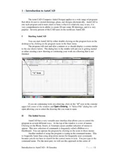
1 Isometric Drawings in AutoCAD R Greenlee Page | 1 Chapter 7 Isometric Drawings In this assignment, we are going to look at creating Isometric Drawings with AutoCAD. These drawing appear to be three dimensional but they are not. An AutoCAD Isometric drawing is a 2 dimensional drawing just like a paper drawing. AutoCAD provides some tools to aid us in creating the drawing, but not very many. Mostly, we will be using the same commands that we used in creating orthographic Drawings . We are going to draw the figure shown on the right. We will use the dimensions shown on the figure and make a drawing that is dimensionally correct as we have done in the past. We will start by drawing an Isometric box that makes up the main body of the object. From there, we will add the semicircular hole at the bottom and the half cylinder at the top. The first thing we need to do is to put AutoCAD in the Isometric mode. This mode is entered through the SNAP command.
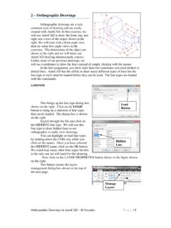
2 SNAP ON/OFF/Rotate/Stype < > S {Put into Isometric mode} Standard/ Isometric I Vertical Spacing < > .4 SNAP ON/OFF/Snap OFF {Stop snapping to grid points} Now we can draw the left face of the box. Use the line command and click on the lower right corner of the right face of the box. We will use polar coordinates to make the lines at 30 degree angles. line From Point: {Click on the screen where you want the object to start} To Point: @5<150 To Point: To Point: @5<330 To Point: C Start here Isometric Drawings in AutoCAD R Greenlee Page | 2 Next draw the right face of the box. In one of the earlier lessons, we turned on the snapping to the endpoint of a line with the OSNAP command. You can achieve the same thing by typing end when the program is expecting a point. Press return after typing end then click on the end point of a line , arc, or circle. line From Point: end {type this to tell the program that you want to use the end point of a line to start the new line that you are drawing} of {click on the starting point above} To Point: To Point: To Point: The top of the box will be drawn next.
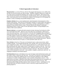
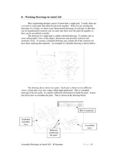
3 We will start with the top right corner of the box we have just finished drawing. line From Point: end of {click on upper right point of box} To Point: @5<150 To Point: end of {complete point by clicking on end of the correct point} When you have finished, you should have a box like the one shown on the right. Next we need to draw the arcs making up the object. These are actually ellipses because of the Isometric view. We use the ELLIPSE command to draw them. AutoCAD does not draw elliptical arcs but it does draw complete ellipses and we can trim these to create elliptical arcs. We will start with the arc at the bottom of the box shown in the Start hereEnd here Stop here Start here Isometric Drawings in AutoCAD R Greenlee Page | 3 picture at the right. Use the CTRL E key combination to change the mouse pointer so that the lines are parallel with the edges of the right face (<Isoplane right>). ELLIPSE <axis end point 1>/Center/Isocircle: I Center of circle: MID {We want the center of the Isocircle to be at the midpoint of the line } of {select the line at the bottom of the right face} <Circle radius>/Diameter.
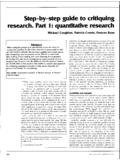
4 75 Now we can erase the part of the ellipse we do not need with the TRIM command. TRIM Select cutting edge(s).. Select objects: {select the line } Select objects to trim: {select bottom of circle} TRIM Select cutting edges .. Select objects: {select upper half of isocircle} Select object to trim {Select the line through the isocircle} Select object to trim Midpoint of LineIsocircle Cutting edge Part to trim Cutting edge Part to trim Isometric Drawings in AutoCAD R Greenlee Page | 4 We need to add a line at the bottom edge of the arc. We can do this by drawing a line that is too long then trimming it with the TRIM command. This will complete the bottom part of the object. line From point: END of {select end of arc} To point: @3<150 TRIM {Select the arc as the cutting surface and trim the line that we have just drawn. The arc and line are shown in the figure below} We must start on the half cylinder that intersects the top of the block.
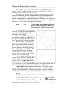
5 We will do this by drawing four ellipses along the side of the block. Use the CTRL E command to place the mouse pointer lines parallel to the edges of the left face of the box. ELLIPSE <Axis endpoint 1>/Center/Isocircle: I Center of circle: MID of {Select top left edge of box} <Circle radius>/Diameter: 1 Add this line Isometric Drawings in AutoCAD R Greenlee Page | 5 Repeat the ELLIPSE command to create the larger, 3 inch diameter ellipse then repeat it two more times to create the ellipses on the other side of the box. After you have draw the ellipses, trim their tops with the TRIM command. Use the edges of the box as the cutting planes. The figure on the right shows the isocircles after trimming. The next step is to form the ends of the half cylinder shape. We can do this by moving the inside diameter arcs to the ends of the cylinder and copying the outside diameter arcs to the ends of the cylinder.
6 MOVE Select objects: {Select the inner circles on the left side} Base point or displacement: END of {Select the end of the inside arc} Second point of displacement: Repeat this command for the other side and move the inside arc .75 inches at an angle of 30 degrees. Next copy the outside diameter arcs to their end positions on the cylinder. You can do this with the COPY command. COPY Select objects: {Select the outer arc on the left side of the object} <Base point of displacement>: END of {Select the end of the arc} Second point of displacement: Copy the arc on the other side of the object using a similar command sequence. When you finish you should have the picture shown on the right. Move these Copy theseIsometric Drawings in AutoCAD R Greenlee Page | 6 Use the TRIM and the ERASE commands to remove the edges of the box that cannot be seen. Next, we will draw the line tangent to the arcs. This line forms the outside edge of the cylinder.
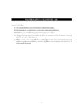
7 Press CTRL E until the mouse pointer lines are parallel to the right face of the box and then type: line Point from: NEAR of {Click on one of the arcs as close as you can to the tangent You may have to zoom in on the arc to select it.} Point to: TAN of {Select the other arc. You should move the mouse pointer as close to the tangent point as possible.} Finally we do a little more trimming and erasing of the arcs on the cylinder and we have the finished drawing shown below. We can now place the view on the drawing sheet by selecting the Layout1 tab at the bottom of the screen and following the procedures we discussed in Chapter 6. Near here Tangent hereIsometric Drawings in AutoCAD R Greenlee Page | 7 Difficult Curves Sometimes when drawing an Isometric view, the curves that you must draw cannot be drawn with an ellipse. A simple example is shown in the drawing below. The curve where the cylinder meets the curved surface cannot be drawn with a simple ellipse or ellipse.
8 It can be drawn however and we will illustrate it with the object shown above. Start by drawing simple Isometric object like the one shown on the right. Use the drawing above for the dimensions of this box. Isometric Drawings in AutoCAD R Greenlee Page | 8 Next we will add two ellipses to either side. The ellipses have a radius of The object with the ellipses is shown on the right. When you have completed the ellipses, trim them so that only the parts that are edges of the object are remaining. The edges of the box can be used as the cutting planes. Next, draw lines connecting the ends of the ellipse segment. These can be easily drawn with the mouse. OSNAP should be set to ON so that the mouse pointer will snap to the ends of the ellipse segments. Isometric Drawings in AutoCAD R Greenlee Page | 9 The cylinder intersects the top plane of the object, and we can draw ellipses at the intersection. The large one has a radius of 2 and the smaller one has a radius of 1.
9 After drawing the ellipses, trim the larger one and the line passing through its center. This is illustrated in the drawing on the right. When you draw the ellipses, you can use the MID command to locate the center of the ellipses at the midpoint of the line passing through their centers. ellipse Specify axis endpoint of ellipse or [Arc/Center/Isocircle]: i Specify center of isocircle: mid of Specify radius of isocircle or [Diameter]: 2 We can now draw a construction line to help us determine the intersection of the cylinder and the curved surface. Switch to the projection layer and add a line that connects the two corners of the box. We are going to create evenly spaced construction lines perpendicular to and along the length of the construction line we have just crated. We will use these lines to help us create a tessellated surface on the cylinder which we can intersect with a tessellated surface on the intersecting curve. We start by creating 10 equally spaced points along the line .
10 This is done with the DIVIDE command. Points are very small and you will probably not be able to see them, just accept the fact that they are there. divide Select object to divide: {Click on the construction line we have just created} Enter the number of segments: 10 {Enter 10 and press return} Construction line Isometric Drawings in AutoCAD R Greenlee Page | 10 Next, we will turn on snapping to points so that AutoCAD can use these 10 equally spaced points as the beginning point of lines needed to construct the tessellated surface. Enter OSNAP to produce the dialog box shown on the right. Click on the Node snap mode then click on OK. Turn ORTHO on and use CTRL-E until the mouse pointer has a line parallel to the back of the object we are drawing. Use the line command to draw the line . The results are shown below. line Specify first point: {Move the mouse over to the first point we created and click} Specify next point or [Undo]: {Extend a line parallel to the back of the object until it crosses the line connecting to the ellipses we drew} Specify next point or [Undo]: {Press Enter} Snap to Node New line Isometric Drawings in AutoCAD R Greenlee Page | 11 Now we can copy this line creating a new line at each of the 10 points we created.