Transcription of Chapter 8: Stormwater Management Design Examples
1 Chapter 8: Stormwater Management Design Examples This Chapter presents Design Examples for two hypothetical development sites in the State of New York. The first site, Stone Hill Estates, is a residential development near Ithaca. The second is a commercial site in Albany. The Chapter is divided into five sections, each of which focuses on a particular element of Stormwater Management Design . Section provides an example of detailed hydrology calculations at the residential site. Section presents a pond Design example based on the hydrology calculated in Section This Design example demonstrates the hydrologic and hydraulic computations to achieve water quality and water quantity control for Stormwater Management . Other specific dam Design criteria such as soil compaction, structural appurtenances, embankment drainage, outlet Design , gates, reservoir drawdown requirements, etc.
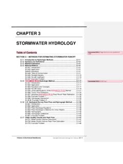
2 Are stated in Guidelines For Design of Dams. This Design example in Section requires an Article 15 Permit from NYS-DEC since the dam is 15 feet high measured from the top of dam to the low elevation at the downstream outlet, and the storage measured behind the structure to the top of the dam is MG. Sections through present Design Examples for three practices on the commercial site: a sand filter, infiltration trench, and bioretention practice. Section Sizing example - Stone Hill Estates Following is a sizing example for the hypothetical Stone Hill Estates, a 45-acre residential development in Ithaca, New York (Figure ). The site also drains approximately 20 acres of off-site drainage, which is currently in a meadow condition. The site is on mostly C soils with some D soils. 8-1 New York State Stormwater Management Design Manual Chapter 8 Figure Stone Hill Site Plan Drainage Area = Off site Drainage = Light Gray Fill/ Hatch Hydrologic Data Pre Post Ult.
3 CN 72 78 82 tc(hr) Base Data Location: Ithaca, NY Site Area = ac; Offsite Area = ac (meadow) Total Drainage Area (A) = Measured Impervious Area= ac; 8-2 New York State Stormwater Management Design Manual Chapter 8 Site Soils Types: 78% C , 22% D Offsite Soil Type: 100% C Zoning: Residential ( acre lots) Hazard Class: Low A , Dam Size small per table #1 Appendix A. Computation of Preliminary Stormwater Storage Volumes and Peak Discharges The layout of the Stone Hill subdivision is shown on the previous page. Water Quality Volume, WQv Compute Impervious Cover Use both on-site and off-site drainage: I = acres = Compute Runoff Coefficient, Rv Rv = + (I) ( ) = + ( ) ( ) = Compute WQv (Includes both on-site and off-site drainage) Use the 90% capture rule with of rainfall.
4 (From Figure ) WQv = ( ) (Rv) (A) = ( ) ( ) ( ac) (1ft/12in) = ac-ft Establish Hydrologic Input Parameters and Develop Site Hydrology (see Figures , , and ) Condition Area CN Tc Ac hrs Pre-developed 72 Post-developed 78 Ultimate buildout* 82 *Zoned land use in the drainage area. 8-3 New York State Stormwater Management Design Manual Chapter 8 Hydrologic Calculations Condition Q1-yr Q1-yr Q10-yr Q100-yr Runoff inches cfs cfs cfs Pre-developed 19 72 141 Post-developed 38 112 202 Ultimate buildout NA NA NA 227 8-4 New York State Stormwater Management Design Manual Chapter 8 Figure Stone Hill Pre-Development Conditions 8-5 New York State Stormwater Management Design Manual Chapter 8 Figure Stone Hill Post-Development Conditions 8-6 New York State Stormwater Management Design Manual Chapter 8 Figure Stone Hill Ultimate Buildout Conditions 8-7 New York State Stormwater Management Design Manual Chapter 8 Compute Stream Channel Protection Volume.
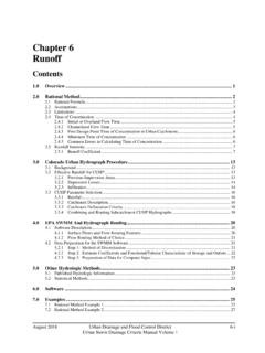
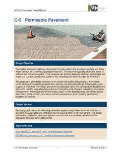
5 (Cpv) (see Section and Appendix B) For stream channel protection, provide 24 hours of extended detention (T) for the one-year event. Compute Channel Protection Storage Volume First, determine the value of the unit peak discharge (qu) using TR-55 and Type II Rainfall Distribution Initial abstraction (Ia) for CN of 78 is : [Ia = (200/CN - 2)] Ia/P = ( )/ inches = Tc = hours Using the above data and Exhibit 4-II from TR-55 (NRCS, 1986), qu = 570 csm/in (cubic feet per second per square mile per year) Knowing qu and T = 24 hours, find qo/qi using Figure (also see methodology in Appendix B) Peak outflow discharge/peak inflow discharge (qo/qi) = Vs/Vr = - (qo/qi) + (qo/qi) 2 - (qo/qi) 3 (from Appendix B) Where Vs equals channel protection storage (Cpv) and Vr equals the volume of runoff in inches. Figure Detention Time vs. Discharge Ratios (Source: MDE, 2000) 8-8 New York State Stormwater Management Design Manual Chapter 8 Vs/Vr = and, from figure , Q = Solving for Vs Vs = Cpv = ( )(1/12)( ac) = ac-ft (104,214 cubic feet) Define the Average Release Rate The above volume, ac-ft, is to be released over 24 hours ( ac-ft 43,560 ft2/ac) / (24 hrs 3,600 sec/hr) = cfs Compute Overbank Flood Protection Volume, (Qp10) (see Section ) For both the overbank flood protection volume and the extreme flood protection volume, size is determined using the TR-55 Short-Cut Method, which relates the storage volume to the required reduction in peak flow and storm inflow volume (Figure ).
6 For a qi of of 112 cfs (post-developed), and an allowable qo of 72 cfs (pre-developed), the value of (qo)/(qi) is Using figure , and a post-developed curve number of 78, Vs/Vr = Using a total storm runoff volume of 427,155 cubic feet ( acre-feet), the required storage (Vs) is: Vs = Qpv = (427,155)/43,560 = acre-feet While the TR-55 short-c ut method reports to incorporate multiple stage structures, experience has shown that an additional 10-15% storage is required when multiple levels of extended detention are provided inclusive with the 10-year storm. So, for preliminary sizing purposes add 15% to the required volume for the 10-year storm. Qp-10 = = ac-ft. While the TR-55 short-cut method reports to incorporate multiple stage structures, experience has shown that an additional 10-15% storage is required when multiple levels of extended detention are provided inclusive with the 10-year storm.
7 So, for preliminary sizing purposes, add 15% to the required volume for the 10-year storm. Qp-10 = = ac-ft. 8-9 New York State Stormwater Management Design Manual Chapter 8 Figure Approximate Detention Basin Routing for Rainfall Types I, IA, II, and III Source: TR-55, 1986 Compute Extreme Flood Protection Volume, (Qf) Extreme flood protection is calculated using the same methodology as overbank protection. For a Qin of, and an allowable Qout of, and a runoff volume of the Vs necessary for 100-year control is, under a developed CN of 78. Note that inches of rain fall during this event, with approximately inches of runoff. While the TR-55 short-cut method reports to incorporate multiple stage structures, experience has shown that an additional 10-15% storage is required when multiple levels of extended detention are provided inclusive with the 100-year storm.
8 So, for preliminary sizing purposes add 15% to the required volume for the 100-year storm. Qf-100 = = ac-ft. Analyze Safe Passage of 100-Year Design Storm (Qf) If peak discharge control of the 100-year storm is not required, it is still necessary to provide safe passage for the 100-year event under ultimate buildout conditions (Qult = 227 cfs). See table 4-1 appendix A for low and moderate hazard dam Design storm. 8- 10 New York State Stormwater Management Design Manual Chapter 8 Section Pond Design example Following is a step-by- step Design example for an extended detention pond (P-3) applied to Stone Hill Estates, which is described in detail in Section along with Design treatment volumes. This example continues with the Design to develop actual Design parameters for the constructed facility.
9 Step 1. Compute preliminary runoff control volumes. The volume requirements were determined in Section Table provides a summary of the storage requirements. Table Summary of General Storage Requirements for Stone Hill Estates Symbol Category Volume Required (ac-ft) Notes WQv Water Quality Volume Cpv Stream Protection Average ED release rate is cfs over 24 hours Qp Peak Control 10-year, in this case Qf Flood Control Step 2. Determine if the development site and conditions are appropriate for the use of a Stormwater pond. The drainage area to the pond is acres. Existing ground at the proposed pond outlet is 619 MSL. Soil boring observations reveal that the seasonally high water table is at elevation 618. The underlying soils are SC (sandy clay) and are suitable for earthen embankments and to support a wet pond without a liner. The stream invert at the adjacent stream is at elevation 616.
10 Step 2A. Determine Hazardous Class of Dam. The height of the dam, its maximum impoundment capacity, the physical characteristics of the dam site and the effect that a failure of the dam would have upon human life, residences, buildings, roads, highways, utilities and other facilities should be assessed to determine whether a low (A), moderate (B) or high (C) hazard classification is appropriate for designing the dam. Refer to Section of the "Guidelines for the 8- 11 New York State Stormwater Management Design Manual Chapter 8 Design of Dams" for additional information regarding hazard class and Table 1 of those guidelines for the appropriate hydrologic Design criteria for new dams based on the assigned hazard class and size. Step 3. Confirm local Design criteria and applicability.