Transcription of Chapter 9 Hydraulic Structures - UDFCD
1 September 2017 Urban Drainage and Flood Control District 9- i Urban Storm Drainage Criteria Manual Volume 2 Chapter 9 Hydraulic Structures Contents Structures in Streams .. 1 Grade Control Structures .. 2 Overview .. 2 Simplified design Procedures for Drop Structures .. 4 Introduction .. 4 5 Unit Discharge .. 6 Longitudinal Slope of the Drop structure 6 Stilling Basin .. 6 Seepage Analysis and Cutoff Wall design .. 7 Low-flow Channel .. 8 Detailed Drop structure Hydraulic Analysis .. 8 Introduction .. 8 Cross Section Placement .. 9 Mannings s Roughness Coefficient for Drop 10 Hydraulic Jump Formation .. 11 Hydraulic Jump Length .. 13 Evaluation of Low-flow Channel versus 14 Evaluate Additional Return Period Flow Rates .. 15 Rock Sizing for Drop Approach and Downstream of End Sill .. 15 Seepage Control .. 15 Introduction .. 15 Weep Drains .. 15 Lane s Weighted Creep Method.
2 15 Foundation/Seepage Control Systems .. 17 Detailed Force Analysis .. 18 Grouted Stepped Boulder Drop Structures .. 23 Description .. 23 structure Complexity .. 23 design Criteria .. 23 Construction Guidance .. 25 Sculpted Concrete Drop structure .. 32 Description .. 32 structure Complexity .. 32 design Criteria .. 33 Decorative Elements (Finishing) .. 36 Construction Guidance .. 40 Vertical Drop structure Selection .. 49 Description .. 49 design Criteria .. 49 Low-flow Drop Structures and Check Structures .. 54 Pipe Outfalls and Rundowns .. 58 Pipe End Treatment .. 58 Flared-End Sections and Toe Walls .. 58 9- ii Urban Drainage and Flood Control District September 2017 Urban Storm Drainage Criteria Manual Volume 2 Concrete Headwall and Wingwalls .. 59 Energy Dissipation and Erosion Protection .. 65 Riprap Apron .. 66 Low Tailwater Basin .. 71 Rock Sizing for Riprap Apron and Low Tailwater Basin.
3 73 Outfalls and Rundowns .. 75 Rundowns .. 86 References .. 87 Appendix A. Force Analysis for Grade Control Tables Table 9-1. design criteria for drop Structures using simplified design procedures .. 5 Table 9-2. Approximate Manning s roughness at design discharge for stepped drop structure .. 10 Table 9-3. Lane s weighted creep: Recommended minimum ratios .. 17 Table 9-4. Boulder sizes for various rock sizing parameters .. 25 Table 9-5. Comparison of concrete and shotcrete .. 35 Table 9-6. Nominal limit of maximum pressure fluctuations within the Hydraulic jump (Toso 1986) .. 97 Figures Figure 9-1. Stilling basin length based on unit discharge (for simplified design procedure) .. 7 Figure 9-2. Sample HEC_RAS profile with cross section locations for Hydraulic analysis .. 9 Figure 9-3. Recommended Manning s n for flow over B24 to B42 grouted boulders .. 11 Figure 9-4. Length in terms of sequent depth of jumps in horizontal channels.
4 13 Figure 9-5. Stilling basin profile .. 14 Figure 9-6. Sample HEC-RAS output for cross section located at drop crest .. 14 Figure 9-7. Sheet pile cutoff wall upstream of drop structure .. 19 Figure 9-8. Sheet pile cutoff wall connections between boulders .. 20 Figure 9-9. Concrete or grout cutoff wall upstream of drop structure .. 21 Figure 9-10. Weep drains .. 22 Figure 9-11. Example plan view of basic grouted stepped boulder drop structure .. 27 Figure 9-12. Cross sections of basic grouted stepped boulder drop structure .. 28 Figure 9-13. Cross sections of basic grouted stepped boulder drop structure .. 29 Figure 9-14. Example of complex grouted stepped boulder drop structure .. 30 Figure 9-15. Grouted boulder placement detail .. 31 Figure 9-16. Example plan view of basic sculpted concrete drop structure .. 42 Figure 9-17. Example profiles of basic sculpted concrete drop structure .. 43 Figure 9-18.
5 Example cross sections of basic sculpted concrete drop structure .. 44 Figure 9-19. Example plan view of complex sculpted concrete drop structure .. 45 Figure 9-20. Example detailed view of complex sculpted concrete drop 46 Figure 9-21. Rebar placement for sculpted concrete drop Structures .. 47 Figure 9-22. structure edge wall details .. 48 Figure 9-24. Example vertical drop structure plan .. 52 Figure 9-25. Example vertical drop structure sections .. 53 Figure 9-26. Check structure details (Part 1 of 3) .. 55 September 2017 Urban Drainage and Flood Control District 9- iii Urban Storm Drainage Criteria Manual Volume 2 Figure 9-27. Check structure details (Part 2 of 3).. 56 Figure 9-28. Check structure details (Part 3 of 3).. 57 Figure 9-29. Flared end section (FES) headwall concept .. 60 Figure 9-30. Flared end section (FES) headwall concept .. 61 Figure 9-31. Pipe headwall concept .. 62 Figure 9-32.
6 Pipe headwall with boulders concept .. 63 Figure 9-33. Pipe headwall/wingwall concept .. 64 Figure 9-34. Riprap apron detail for culverts in-line with the channel .. 68 Figure 9-35. Expansion factor for circular conduits .. 69 Figure 9-36. Expansion factor for rectangular conduits .. 70 Figure 9-37. Low tailwater riprap basin .. 72 Figure 9-38. Riprap erosion protection at circular conduit outlet (valid for ) .. 74 Figure 9-39. Riprap erosion protection at rectangular conduit outlet (valid for ) .. 75 Figure 9-40. Boulder outfall detail .. 76 Figure 9-41. Boulder outfall detail (in-line with channel) .. 77 Figure 9-42. Impact stilling basin for pipes smaller than 18 in diameter .. 81 Figure 9-43. Modified impact stilling basin for conduits 18 to 48 in diameter (Part 1 of 2) .. 82 Figure 9-44. Modified impact stilling basin for conduits 18 to 48 in diameter (Part 2 of 2) .. 83 Figure 9-45.
7 UDFCD modified USBR type VI impacts stilling basin (general design dimensions) .. 84 Figure 9-46. Basin width diagram for the USBR type VI impact stilling basin .. 85 Appendix A Figure A-1. Coefficient of pressure fluctuation, Cp, at Hydraulic jump .. 98 Figure A-2. Coefficient of pressure fluctuation, Cp, normalized for consideration of slope and jump beginning slope .. 99 Chapter 9 Hydraulic Structures September 2017 Urban Drainage and Flood Control District 9- 1 Urban Storm Drainage Criteria Manual Volume 2 Structures in Streams Hydraulic Structures are used to guide and control water flow in streams. Structures described in this Chapter consist of grade control Structures and outfall Structures for various applications and conditions. The discussion of grade control Structures in this Chapter addresses the Hydraulic design and grouted boulder, sculpted concrete, and vertical drop Structures , whereas the Open Channels Chapter discusses the placement of grade control Structures in the stream and the Stream Access and Recreational Channels Chapter covers safety considerations relevant to all urban streams and specialized design of boatable Hydraulic Structures .
8 The outfalls section provides design guidance for various types of pipe end treatment and rock protection to dissipate Hydraulic energy at outfalls of storm drains and culverts. Related design information is covered in the Streets, Inlets, and Storm Drains and Culverts and Bridges Chapters. Considered environmental, ecological, and public safety objectives in the design of each structure . The proper application of Hydraulic Structures can reduce initial and future maintenance costs by managing the character of the flow to best meet all project needs. The shape, size, and features of Hydraulic Structures vary widely for different projects, depending upon the design discharge and functional needs of the structure . Hydraulic design procedures discussed herein govern design of all Structures . For the design of unique Structures that may not fit the guidance provided, Hydraulic physical modeling or computational fluid dynamics (CFD) modeling may be beneficial.
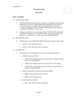
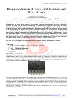
9 Photograph 9-1. This grouted boulder drop structure exemplifies the opportunity available for creating an attractive urban Hydraulic setting for a riparian corridor. Guidance for Using this Chapter Determine if the project can be designed using the simplified method (Section ) or if a detailed design is required (Section ). Perform soils and seepage analyses as necessary for the design of the foundation and seepage control system (Section ). Additional analysis of forces acting on a structure may be necessary and should be evaluated on a case-by-case basis (Section ). Use criteria specific to the type of drop structure to determine the final flow characteristics, dimensions, material requirements, and construction methods. Refer to Section for Grouted Stepped Boulder (GSB) drop Structures or to Section for Sculpted Concrete (SC) drops. Refer to the Trails and Recreations Channels Chapter for design of boatable Structures and other criteria required for public safety.
10 Hydraulic Structures Chapter 9 9- 2 Urban Drainage and Flood Control District September 2017 Urban Storm Drainage Criteria Manual Volume 2 Grade Control Structures Overview As discussed in the Open Channels Chapter , urbanization increases the rate, frequency and volume of runoff in natural streams and, over time, this change in hydrology may cause streambed degradation, otherwise known as down cutting or head cutting. Stabilization improvements to the stream are necessary prior to or concurrent with development in the watershed. Stream stabilization is the third step of the Four Step Process to Stormwater Management (see Chapter 1 of Volume 3 of this manual). Drop Structures are broadly defined. Drop Structures provide protection for high velocity Hydraulic conditions that allow a drop in channel grade over a relatively short distance. They provide controlled and stable locations for a Hydraulic jump to occur, allowing for a more stable channel downstream where flow returns to subcritical.