Transcription of Chapter 9 - Testing Dust Control Systems
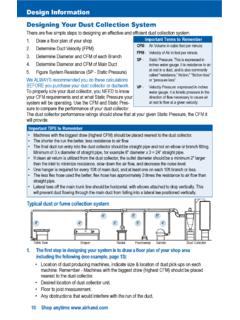
1 Chapter 9 Testing dust Control Systems Reason For Testing Testing is necessary to evaluate the effectiveness of dust Control measures. In general, Testing is performed to- Determine if the system is operating as it was designed to operate Evaluate the system 's effectiveness in reducing dust concentrations and employee exposure to dust dust collection system Testing Testing a dust collection system primarily involves airflow measurement. It can provide data necessary to- Evaluate whether the system is performing in accordance with the design Set blast gates properly and adjust airflows Identify maintenance needs Determine the system 's capacity for additional exhaust hoods Design and operate future installations effectively Test Procedure Testing can be performed by obtaining airflow and pressure measurements at selected locations in the system . The following steps should be conducted: Obtain original design drawings and calculations or prepare a sketch of the system to indicate size, length, and relative location of all dusts, fittings, and associated hardware and system components.
2 Use the drawings as a guide in selecting airflow measuring points and identifying incorrect installation or poor design. Measure the following: Air velocity and static pressure in each branch and main Static and total pressure at the fan inlet and outlet Differential pressure between the inlet and outlet of the dust collector Analyze these measurements to find any changes from the original designs, such as a change in velocity in the branch or a change in the air volume exhausted through the hood. Common problems that can reduce the performance of dust collection system and their remedies are shown in the troubleshooting chart on the following page. 1 Airflow Measurements Airflow inside the ductwork is usually not uniform; therefore, it is necessary to obtain velocity pressure measurements at several points within the dust cross-section. The following procedure should be used to measure velocity pressure: Divide the dust cross-section into equal areas.
3 The suggested equal area grids for circular or rectangular ducts are illustrated. Obtain velocity pressure measurements at the center of each of these areas. Convert the velocity pressure measurements into air velocities using the following relationship: Average the air velocities to obtain an average velocity (ft/min). Measure the inside duct diameter and calculate the cross-sectional area (ft2). Multiply the duct cross-sectional area and avelocity to obtain airflow in cubic feet per minute. verage Troubleshooting Chart-Reduction in dust collection system Performance Symptom Cause Remedy Reduced air volume Ducts plugged. Clean out ducts, check air velocities, and check design specifications. Reduced fan speed due to belt slippage. Check belt tension and adjust it according to manufacturer's recommendations. Wear or accumulations on rotor or fan casing that would obstruct airflow.
4 Replace or clean the worn-out equipment; consult manufacturer to see if fan is correct for the application. Leakage in the ductwork due to loose clean-out doors, broken joints, or worn-out ductwork. Replace or repair leaking and worn-out sections of ductwork. Additional exhaust points added to the system . Redesign or rebalance the system . Change of blast gates setting in Reset the blast gates according to 2branch lines. original design and lock them in place. Increased pressure drop across dust collector. Refer to operation and maintenance instructions of the dust collector and check its operation. Points to Note:The smaller the equal areas, the more accurate the measurement. An approved method for obtaining velocity pressure is tmake two traverses, at right angles to each other, with a probe (such as a Pitot tube) across the diameter of the duct. o0 Wherever possible, the traverses should be made at 8 or more duct diameters away from any major air disturbances, such as an elbow, hood, or branch entry.
5 Correction for air densities should be made when air is at nonstandard conditions. For example, it is necessary to correct for air densities when: Moisture content is greater than lb/lb of dry air. Temperature of the air stream varies more than 3F from the standard temperature. Altitude is greater than 1,000 ft above mean sea level. dust in the air may affect the instrument performance. Static pressure measurements are made either by inserting a probe inside the ductwork or by holding a piece of tubing tightly against a small static pressure opening in the side of the duct with its other end connected to a pressure-measuring device. The characteristics of the static pressure openings in the ductwork are critical in measuring static pressure. Points to Note: 3 The static pressure openings should be: - Flush with the inner surfaces of the duct wall. - Drilled and not punched. - Without burrs or projections on the inner surface.
6 Pressure measurements should not be taken at the heel of an elbow or at other points where, due to excessive turbulence or change in air velocity, there is sudden expansion or contraction of ductwork. Commonly used flow-measuring instruments are summarized in the table below. Flow-Measuring Instruments Instrument Characteristics Advantages/Disadvantages Pilot tube Consists of two concentric tubes: one detects total pressure in the airstream and the other detects static pressure. Used in conjunction with monometer or Aneroid type gauge An extremely useful tool in flow measurement. Does not need calibration. Use in the field is limited at velocities greater than 600-800 ft/min. U-tube manometer Simplest type of pressure gauge. Usually filled with oil or water, but can be used with other fluids such as alcohol, mercury, or kerosene. Usually calibrated in inches of water gauge.
7 Can be used for either portable or staionary applications. Suitable for most static pressure measurements. Use is limited at velocities less than 1,000 ft/min (below .06 in wg). Inclined manometer Improved version of the U-tube manometer. Many commercial versions equipped with a 10:1 slope, built-in level, leveling adjustment, and a means of adjusting scale to zero. The single leg is tilted to obtain increased sensitivity and scale magnification. Accuracy dependent on slope of tube. Consequently, base must be firm enough to permit accurate leveling. Swinging vane anemometer Direct readout instrument used to measure air velocities and static pressures in duct Systems as well as in unrestricted areas. Consists of a meter, a measuring probe, range selectors, and connecting hoses. Velocity range is from 30 to 300 ft/min for a low-flow Can be operated under high temperatures (up to 700 F) and high static pressure (up to 10 ). May require periodic calibration.
8 Presence of dust , moisture, or corrosive material can affect accuracy. A plugged filter increases resistance and the amount of air passed to the 4probe and from 100 to 10,000 ft/min for a Pitot probe. Static pressure ranges are from 0 to in. wg and 0 to 10 in wg. swinging vane may change. Requires a larger diameter hole than the Pitot tube (approximately 5/8 in. diameter vs. 1/4 in. to 3/8 in. for the Pitot tube). Heated wire anemometer Operates on principle that resistance of a wire varies with temperature and degree of temperature change is proportional to velocity of air passing over the wire. Direct readout instrument. Has short response time (less than 1 minute). Is portable. velocity range is from 10 to 8,000 ft/min. Static pressure range is up to 10 Temperature range is from 0 to 255 F. Applicable for field and laboratory use. Integrity of probe must be maintained; the delicate wire can easily be damaged by mechanical shock, heavy dust loadings, or corrosive materials.
9 Requires periodic calibration. Aneroid type gauge Does not use liquid. Used as field instrument in conjunction with Pitot tubes or other probes. Magnehelic gauge is the most commonly used in field installations. Easy to read. Provides a greater response than manometers. Portable. Requires less maintenance and mounting; allows use in any position without losing accuracy. Subject to mechanical shock and failure. Requires periodic calibration. This information was excerpted from the OSHA website. Safety & Health Administration 200 Constitution Avenue, NW Washington, DC 20210 5