Transcription of Chapter RP-3 - NukeWorker
1 RP-3 Page 1 of 28 rev November 2005 radiation Protection radiation detection and Instrumentation TABLE OF CONTENTS INTRODUCTION OBJECTIVES BASIC DETECTORS SIX REGION CURVE RECOMBINATION REGION IONIZATION CHAMBER REGION PROPORTIONAL AND LIMITED PROPORTIONAL REGIONS GEIGER-MUELLER REGION CONTINUOUS DISCHARGE REGION DETECTOR CHARACTERISTICS detection AND PERSONNEL MONITORING SCINTILLATION DETECTORS SEMI-CONDUCTOR detection SYSTEMS NEUTRON detection PERSONNEL MONITORING FILM BADGES THERMOLUMINESCENT DOSIMETERS DIRECT READING DOSIMETERS PHYSICAL AND ELECTRONIC DISCRIMINATION DETECTOR CHARACTERISTICS SUMMARYC hapter RP-3 radiation protection radiation detection AND INSTRUMENTATION Chapter RP-3 RP-3 Page 2 of 28 rev November 2005 INTRODUCTION We have learned that ionizing radiation has the ability to transfer energy to the material through which it passes.
2 If the radiation were to pass through human tissue, that tissue would absorb some energy. The absorption of energy is not enough to stimulate nerve endings, so we could be exposed to large amounts of radiation and not feel our bodies absorbing the energy. In fact, we could receive a lethal dose of radiation and not know it until the effects became apparent hours or days later. If we cannot detect radiation as we can detect smell, heat, or light, how do we know if we are exposed to radiation ? Obviously, we need an instrument to do the detecting. This lesson will discuss radiation detection instrumentation construction and operation.
3 radiation protection radiation detection AND INSTRUMENTATION Chapter RP-3 RP-3 Page 3 of 28 rev November 2005 OBJECTIVES TERMINAL OBJECTIVE The Contractor Health Physics Technician will be able to select the appropriate radiation survey instrument for a given job and justify why the selected instrument was chosen. The Contractor Health Physics Technician will describe the basic concepts of dosimetry and the principles of operation and characteristics of the various types of dosimetry. ENABLING OBJECTIVES Upon completion of this lesson, the Contractor Health Physics Technician will be able to: 1. Explain how ionization can be used to detect radiation .
4 2. Explain the basic principal of operation for a typical gas-filled detector circuit. 3. Describe the basic operating characteristics of the ionization chamber. 4. Describe the basic operation characteristics of a proportional counter. 5. Explain how a proportional counter can discriminate between different types of radiation . 6. Explain how a proportional counter can be made to measure neutron dose rates. 7. List the radiation measurement instruments in the plant that use proportional counters. 8. Describe the basic operating characteristics of a Geiger-Mueller detector. 9. Explain why scintillation detectors are more sensitive than gas-filled detectors.
5 10. Explain the basic operation of a scintillation detector. 11. Explain the basic operation of a semi-conductor detector. 12. Define MDC, MDA, and LLD using the terminology of radiological counting. 13. Describe errors and problems inherent in relating dosimeter readings to actual dose. 14. Describe the principles of operation and characteristics of: a. Thermoluminescent dosimeters (TLD's) b. Pocket Ion Chambers c. Extremity Monitors ( , finger rings) 15. Describe the methods used to assess beta dose. 16. Describe the advantages and disadvantages of a TLD. radiation protection radiation detection AND INSTRUMENTATION Chapter RP-3 RP-3 Page 4 of 28 rev November 2005 BASIC DETECTORS It would be difficult to design an instrument that would directly measure gamma photons or any other type of radiation for that matter.
6 As we have learned, a gamma photon is a packet of energy. How could we measure it? We do not measure the radiation directly but measure it's effects on the material through which it passes. We do this by measuring the ionization that occurs in a material through which radiation passes. radiation detection instruments consist of three basic parts: A detector chamber A power supply/amplification system A measuring device/meter As radiation passes through the detector chamber it will interact with either the chamber walls or the material with the chamber. The output of the chamber is amplified and processed by the measuring device giving us a useful reading of the amount of radiation present.
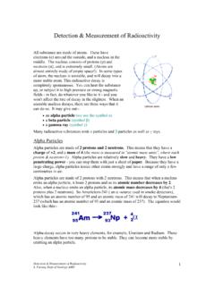
7 The reading can tell us the relative intensity of the radiation present. Since this is not an electronics course, we will not discuss how the actual amplification and measurement is accomplished. We will explore the principles of radiation detection and the characteristics of different types of detectors. As you will remember, ionization is the production of ion pairs a positively charged ion and a negatively charged ion. detection systems that measure ionization have the same basic components as other radiation detection systems. Figure RP-3-1 is a schematic of this type of system. RP-3-1 Basic System for Measuring Ionization The battery (power supply) in the circuit effectively creates positive and negative poles (or electrodes) at the detector.
8 The center wire or rod is the positive electrode and the walls of the chamber are the negative electrode. As the figure shows, the positive radiation protection radiation detection AND INSTRUMENTATION Chapter RP-3 RP-3 Page 5 of 28 rev November 2005 electrode is isolated from the negative electrode. If ionizing radiation (such as a beta chamber, it will interact with the material within the chamber (usually a gas) and ion pairs will be formed. Because of the voltage differential across the electrodes, the positive ions will flow to the negative walls of the chamber, and the negative ions will flow to the positive electrode in the chamber.)
9 This ion collection results in a current flow through the circuit. As current flows through the circuit, the measuring device (meter) will deflect in proportion to the amount of ionization taking place in the chamber. This results in a useful indication of the amount of radiation that is present. When the first ions reach the electrodes, there will be a small current flow. As more and more ions reach the electrodes, the magnitude of the current flow increases until it reaches a peak. Then the number of ions reaching the electrodes begins to decrease, and the current flow begins to decrease. This goes on until all the ions have reached the electrodes.
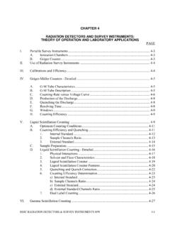
10 If the amount of current measured for a single beta particle is plotted against time, a curve like the one in Figure RP-3-2 will be obtained. This curve is called a pulse. It corresponds to one particle (or wave) of radiation passing through the detector. The size of the pulse varies, depending on the number of ion pairs produced and collected in the detector. The pulse is large if more ion pairs are collected and smaller if fewer ion pairs are collected. RP-3-2 Current Resulting from a Single Beta Many factors affect the number of ion pairs that are produced and conversely the size of the pulse.