Transcription of Characterization of the Technologies for Cogeneration
1 Chapter 4 Characterization of theTechnologies for CogenerationContentsPageintroduction .. 117 Cogeneration Technologies .. 122 Steam Turbines.. 122 Open-Cycle Combustion Turbines .. 125 Closed-Cycle Combustion Turbines .. 127 Combined Cycles .. 129 Diesels .. 131 Rankine Cycle Bottoming .. 133 Fuel Cells .. 137 Stirling Engines .. 139 Use of Alternative Fuels in Cogeneration .. 142 Fluidized Bed Combustion Systems .. 142 Gasification .. 143{interconnection .. 146 Power Quality .. 146 Metering .. 151 Controlling Utility System Operations .. 151 Safety .. 153 Liability .. 154 Summary of RequirementsQuality of interconnectionPage..154 Equipment .. 154 Guidelines for interconnection ~ .. 155 Costs for interconnection .. 157 Summary .. 158 Thermal and Electric Storage .. 159 Thermal .. 159 Electric .. 161 Cogeneration and District Heating.. 163 Chapter preferences .. 165 TablesTable Thermal Analysis of ldeal and RealHeat Engines .. 11822.}
2 Performance Characteristics of AlternativeElectricity-and Steam-ProductionSystems .. 119 Table of Cogeneration Technologies .. 120 Diesel Engine Characteristics .. 131 Estimates of Steam Bottoming CycleOperation and Maintenance Costs .. 136 Cogeneration interconnection Samplecosts .. 157 Interconnection Costs for Three TypicalSystems .. 158 Thermal Energy Storage CapacityRange v. Plant Size.. 160 Cost and Performance Characteristics ofAdvanced Batteries .. 162 Expected Technical and CostCharacteristics of Selected ElectricalEnergy Storage Systems .. Comparison of Energy Utilization in aCogeneration System and a ConventionalPowerplant.. 11917. Steam Turbine Topping System in aCogeneration Configuration .. 12318. Estimated Steam Turbine CogeneratorSystem Installed Costs With DifferentHeat Sources .. 12419. Combustion Turbine .. 12520. Schematic of a Simple Open-CycleCombustion Turbine in a CogenerationApplication .. 12621.
3 Combustion Turbine Cogenerator CostEstimates for the Prime Mover andTotal Installed System .. 12722. Closed-Cycle Gas Turbines With andWithout Regeneration .. 12823. Closed-Cycle Gas Turbine CogeneratorInstalled Cost .. 12924. Schematic of a Combined-CycleCogenerator.. 130 Figure Total Installed Costs for Combined-CycIe Cogenerator Systems .. 13126. Diesel Engine Cogenerator .. 13227. Diesel Cogenerator Total InstalledCosts for Current and AdvancedPrime Movers .. 13328. Steam Rankine Bottoming Cycle .. 13329. Organic Rankine Bottoming Cycle.. 13430. Organic Rankine Bottoming CycleEfficiency-Variation With Peak CycleTemperature .. 13531. Typical Energy Balances for SteamRankine Bottoming Systems .. 13532. Estimated Installed Costs forCondensing and Non-condensing SteamRankine Bottoming Systems .. 13633. Estimated Installed Costs for OrganicRankine Bottoming System.. 13634. Schematic Diagram of a Fuel Cell.
4 13735. Schematic ofa Fuel Ceil Powerplant.. 13836. Representative Performance of FuelCell Powerplants .. 13937. Future Estimates of Total InstalledCosts for Fuel Cell Powerplant Systems.. 14038. Schematic of a Stirling Cycle Engine .. 14039. Waste Heat Availability From DifferentEngines .. 14140. Future Installed Costs for StirlingEngine Cogenerator Powerplants .. 14141. Possible Power System AdditionalEquipment Requirements to ServeQualifying Facilities .. 15542. Low-Temperature Thermal StorageCost per kWht v. Storage Capacity .. 16043. High-Temperature Thermal StorageCost per kWht v. Storage .. 16144. European Cogeneration DistrictHeating System .. 164 BoxA. Thermodynamic Efficiency ofCogeneration.. 118 Chapter 4 Characterization of the Technologies for CogenerationINTRODUCTIONC ogeneration systems recapture otherwisewasted thermal energy, usually from a heat en-gine producing electricity (such as a steam tur-bine, gas turbine, or diesel engine), and use it forspace conditioning, industrial processes, or as anenergy source for another system component(31 ).
5 This cascading of energy use is what dis-tinguishes Cogeneration systems from conven-tional separate electric and thermal energy sys-tems ( , a powerplant and an industrial boiler),or from simple heat recovery strategies. The auto-mobile engine is a familiar Cogeneration systemthat provides mechanical shaft power to movethe car, produces electricity with the alternatorto run the electrical system, and recirculates theengine s otherwise wasted heat to provide com-fort conditioning in the chapter characterizes the technical fea-tures of Cogeneration systems, including an over-view of the general fuel use and energy produc-tion considerations common to all cogenerators,a description of the operating characteristics andcosts of both commercially available and promis-ing future Cogeneration Technologies , and a dis-cussion of ancillary systems such as those forinterconnecting cogenerators with the utility grid,for improving cogenerators fuel flexibility, andfor storing the electric or thermal energy.
6 A moredetailed Characterization of Cogeneration tech-nologies may be found in volume II of this principal technical advantage of cogenera-tion systems is their ability to improve the effi-ciency of fuel use in the production of electricand thermal energy. Less fuel is required to pro-duce a given amount of electric and thermal en-ergy in a single Cogeneration unit than is neededto generate the same quantities of both types ofenergy in separate, conventional Technologies ( , turbine-generator sets and steam boilers).This is because waste heat from the turbine-gen-erator set, which uses a substantial quantity ofthe fuel used to fire the turbine, becomes usefulthermal energy in a Cogeneration system ( ,process steam) rather than being wasted. Tobe sure, this usually requires some reduction inthe amount of electricity produced compared toa stand-alone turbine generator, but this sacri-fice usually is acceptable to gain the 10- to30-percent increase in overall fuel efficiencyoffered by Cogeneration (31 ).
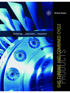
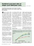
7 To see more clearlyhow this gain is achieved, box A provides a de-tailed look at the thermodynamics of relative efficiency of cogenerators and con-ventional powerplants is shown in figure 16. Ina conventional steam plant (which generally usesa Rankine cycle), energy must be added to thefeedwater in the boiler in sufficient amounts toraise it up to point A in figure 16 (steam for powergeneration). However, due to inherent inefficien-cies in the Rankine cycle turbine, the condens-ing turbines that drive the generators can onlyutilize the amount of energy between points Aand C in the figure (steam at the boiling point)to generate electricity. Thus, the large amountof energy from the boiler feedwater level to pointC is lost as the steam is condensed by coolingwater, carrying off the heat, and rejecting it tothe the Cogeneration plant in figure 16, the en-ergy from A to B (steam) is used to generate elec-tricity, the energy from B to D (water at boilingpoint) is used as process steam, and only the en-ergy from D down to the feedwater level is re-jected to the environment.
8 Thus, the cogeneratorallows use of some of the energy that the conven-tional powerplant otherwise would waste. LevelB is determined by the temperature required forthe process types of cogenerators have differingfuel use characteristics and produce different pro-portions of electricity and steam. The electricity-to-steam (E/S) ratio refers to the relative propor-tions of electric and thermal energy produced by a cogenerator. The E/S ratio is measured in kilo-watthours per million Btu (kWh/MMBtu) of steam(or useful thermal energy), and varies among the117Ch. 4 Characterization of the Technologies for Cogeneration 119 Figure 16. Comparlson of Energy Utilization In a Cogeneratlon Systemand a Conventlonal PowerplantA. Energy level at which steam for power generation Is producedB. Energy level at which process steam is made availableC. Steam at boiling point D.
9 Water at boiling point Feedwater (energy added) Electricity only(conventional powerplant)Electricity(cogeneratand steamion plant)SOURCE: Dow Chemical Co., et al., Energy industrial Canter Study (Washington, D. C.: National Science Foundation, June 1975).120 l Industrial and Commercial Cogenerationdifferent types of Cogeneration Technologies (seetable 23).The total heat rate refers to the total amountof fuel (measured in Btu) required to produce 1kwh of electricity, with no credit given for theuse of waste heat. The net heat rate (alsomeasured in Btu/kWh) credits the thermal out-put and denotes the fuel required to produceelectricity, beyond what would be needed to pro-duce a given quantity of thermal energy in a sep-arate facility ( , a boiler). In a central power-plant, where no heat is recovered, an averagetotal heat rate is 10,500 Btu/kWh (60).
10 Cogenera-tors have a net heat rate of about 4,300 to 7,500 Btu/kWh depending on the characteristics of thethermal energy produced. Thus, depending onthe cogenerator type and how completely thethermal output is utilized, electricity can be pro-duced by a cogenerator with about one-half tothree-fourths the fuel used in central power gen-eration (45,60). Fuel use efficiency for a cogener-ator gives credit to the thermal output; hence itis the ratio of electric output plus heat recoveredin Btu to fuel input in 21 presents a numerical example of heatrates and fuel efficiency-based on modern steamturbines that compares: 1 ) an ideal engine ex-hausting to a low temperature, 2) a real engineexhausting to a low temperature (typical of a util-ity powerplant), 3) a real engine exhausting at ahigher temperature with the heat wasted (some-thing that is best to avoid), and 4) a real engineexhausting at a higher temperature with the heatutilized (as with a cogenerator).