Transcription of Chassis Cab VSIM Usage Instructions Ram Trucks| Ram ...
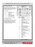
1 Chassis Cab vsim Usage Instructions Ram Trucks| Ram Engineering | vehicle system interface module Video vsim ( vehicle system interface module ) Usage Instructions Overview: The RAM truck engineered upfitter module called the vsim ( vehicle system interface module ) with sales code XXS is standard with Ambulance Prep (sales code AH2), a must have option with PTO Prep (sales codes LBN or LBV), and is available as a stand-alone option. It provides a multitude of useful I/O s to increase upfitter friendliness and upfit simplification. Vehicles not ordered with this option from the factory cannot be retrofitted. Specifics supplied below: drawings showing the module location within the dash vsim includes an upfitter wire harness kit (part number 68319578AA) consisting of four separatecolor coded harness bundles.
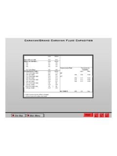
2 Each individual color harness must only be plugged into itscorresponding vsim connector cavity, see photos below showing harness color photo of the four individual color coded vsim upfitter harness bundles. Note that in a fewinstances an individual wire color is duplicated within a bundle these duplications are furtheridentified with a paper flag showing its circuit number. It s recommended that the upfitter, uponharness bundle routing direction determination(s), install additional harness bundle abrasionprotection over each bundle (such as harness convolute). showing module installation within a vehicle and harness chart below delineates the circuits within each color harness bundle, circuit number, signal, wireinsulation colors, maximum allowable amperage per circuit, and circuit chart below delineates the available 250K J1939 Bus 3: PTO idle speed circuits W541, W542, W543 can only be programmed to function if thevehicle was built with PTO option sales codes LBN or Chassis Cab vsim Usage InstructionsBlunt cut and heat shrunk insulations.
3 To be cut off as necessaryDuplicate wire color circuit # tagVSIM Chassis Cab vsim Usage InstructionsVSIMGREYHARNESSGREEN HARNESSBROWN HARNESSBLACKHARNESS Chassis Cab vsim Usage InstructionsGREYHARNESSGREENHARNESSBROWN HARNESSNote: Wheninserting theVSIM harnessBLACK connectors anHARNESS audible click will be heardwhen theconnector isfully UsedNot Used2 Hazard indicator on - HSD outputW719 OutputOpen circuit when hazard flashers are off, battery positi ve voltage (+12V) when hazard flashers are out of "Park" - HSD OutputOpen circuit when gear selector is i n Park , battery positi ve voltage (+12V) when the gear selector is in any other position. 4 Diesel Regeneration (DPF) on - HSD outputW545 OutputOpen circuit when diesel regeneration is not energized battery positive voltage (+12V) when it is energized5 PTO on indicator - HSDW743VT/TN1 HSD OutputOpen circuit when PTO circuit is not energized, battery positive voltage (+12V) when PTO circuit is energized (W708 must be grounded [via PTO pressure switch) for this to function) output6 MIL lamp on - HSD outputW540 OutputOpen circuit when MIL is not illuminated battery positi ve voltage (+12V)]
4 When MIL is illuminated7 Transmission "Par k" positi on - LSD outputW700 OutputOpen circuit when gear selector i s not in Park, grounded when in "Neutral " positi on - LSD outputW701 OutputOpen circuit when gear selector is not in Neutral, grounded when in - A/C Clutch engaged - LSD outputW652 OutputOpen circuit when A/C Clutch is not engaged, grounded when ** CAN communication J1939 + 250 KbaudW532BR/DBJ1939 Bus (+)250 Kbaud J1939 CAN+, use in conjunction with W534, refer to J1939 spreadsheet for available ** CAN communication J1939 - 250 KbaudW534 Bus (-)250 Kbaud J1939 CAN-, use in conjunction with W532, refer to J1939 spreadsheet for available "Reverse" Position - LSD outputW702 OutputOpen circuit when gear selector is not in Reverse, grounded when in UsedNot Used14 HVAC - when A/C is selected via the dash switch - LSD outputW654 OutputOpen circuit when A/C has not been selected, grounded when A/C has been Lamp Output (timer) - LSD outputW711 OutputActivated (grounded) when circuit W506 (cavity 4 of brown connector) is grounded.
5 Open circuit when off. Times out after 30 minutes. Re-enabled by cycling W506 "Drive" Position - LSD outputW703 OutputOpen circuit when gear selector is not in Drive, grounded when in Door Ajar - HSD outputW720 OutputOpen circuit when all the doors are closed, battery voltage (+12V) when any door is UsedNot Used19 Not UsedNot Used20 Not UsedNot Used21 Not UsedNot Used22 Not UsedNot Used23 Not UsedNot Used24 Not UsedNot UsedVSIM 24 - CAVITY GRAY CONNECTORC avity/Pin #Upfitter vsim SignalCircuit #Wire ColorMax Current (Amps)FunctionType of Signal1 Howler Siren disable - HSD outputW505 LGHSD OutputOpen circuit when vehicle speed is below 25 MPH, battery positive voltage (+12V)
6 When vehicle speed is 25 MPH or activation - HSD outputW513 OutputOpen circuit when horn not pressed (not energized), battery positive voltage (+12V) when pressed (energized).3 Side Airbag deployed - HSDW517 OutputOpen circuit when side airbags have not deployed during current key on cycle, battery positive (+12V) upon airbag deployment during current key on Pressure Monitor active - HSD output applicable only RAM 2500 under 10,000 GVWW622 OutputOpen circuit when Tire Pressure Monitor (TPM) indicator lamp is off, battery positive voltage (+12V) when the TPM indicator lamp is active. 5 Power feed "Off" - HSD OutputOpen circuit when key position is in "Accessory/Run/Start", battery positive (+12) when key is in off position.
7 6 Driver Seat Belt not latched - HSD OutputW710 OutputOpen circuit when the drivers seat belt is latched, battery positive voltage (+12V) when the drivers seat belt is not latched (key must be in "run" Pressure Warning Signal - LSD digital PWM outputW707 Signal LSD PWM OutputOil Pressure Signal: Pulse Width Modulated (PWM) between open circuit and ground, 100 Hz, linear with 0 % PWM = 0 PSI, and 100 % PWM = 147 Gauge - LSD digital PWM Signal LSD PWM OutputBattery Voltage Signal: Pulse Width Modulated (PWM) between open circuit and ground, 100 Hz, linear with 0 % PWM = 5V, and 100 % PWM = Airbag Deployed - HSD ouputW518 OutputOpen circuit when front airbags have not deployed during current key on cycle, battery positive (+12V) upon front airbag deployment during current key on Alarm activation - HSD outputW515 OutputOpen circuit when Panic Alarm is not active, battery positive voltage (+12V) when the Panic Alarm is active (key must be in "off" or "accessory" position).)
8 11 Service Brake Pedal depressedW726 OutputOpen circuit when Service Brake Pedal is not active, battery positive voltage (+12V) when the Service Brake Pedal is feed "Accessory" - HSD outputW734 OutputOpen circuit when key position is in "Off/Run/Start", battery positive (+12) when key is in "Accessory" position. 13 Power feed "Run/Start" - HSD outputW736 OutputOpen circuit when key position is in "Off/Accessory", battery positive (+12) when key is in "Run or Start" position. 14 Fuel Level Signal - LSD digital PWM outputW538 Signal LSD PWM OutputFuel Level Signal: Pulse Width Modulated (PWM) between open circuit and ground, 100 Hz, linear with 0 % PWM = empty tank, and 100 % PWM = full RPM Signal - LSD digital PWM outputW744 Signal LSD PWM OutputEngine RPM Signal : Pulse Width Modulated (PWM) between open circuit and ground, HZ/RPM (12 pulses per minute per 1 RPM) @50% duty MPH speed signal -LSD Transmission "Drive" Position - LSD outputW524 Signal LSD PWM OutputVehicle Speed Signal.
9 Modulation between open circuit and ground, output with 10 Hz/MPH (600 pulses per minute per 1 MPH) @50% duty 16 - CAVITY BLACK CONNECTORC avity/Pin #Upfitter vsim SignalCircuit #Wire ColorMax Current (Amps)FunctionType of Signal1 Cluster/Auxiliary lighting dimmer - LSD digital outputW521BR/WT--Digital Signal LSD PWM Outputuses the vehicles instrument cluster dimmer control - will dim auxiliary lighing: PWM between open circuit and ground, output with, 100Hz, linear with 0% PWM = zero intensity, and 100% PWM = full intensity 2 Door Unlock (All) function - "Unlock" all - LSD outputW722DG/TN--LSD OutputRelay driver, mirrors vehicle unlock All request with a ground potential for 500 ms ( key need not be in switch)3 Auxiliary upfitter added flashing light front output - LSD outputW503TN/VT--LSD OutputRelay driver for front auxiliary light(s), open circuit when W500 is "OFF", grounded on (flash) on/off at 80 flashes per minute ( square wave @ 50% duty cycle)
10 When W500 is Cargo Lamp switch signal - digital Signal Input Switch to Groundcargo lamp ON/OFF, use normally open switch to ground to activate a relay via W711, times out after 30 minutes, re-enable by cycling Wag switch signal rear - digital inputW501BR/VT--Digital Signal Input Switch to Groundwhen grounded actuates Wig Wag vehicle rear stop/turn lamps, 80 flashes per minute ( Hz square wave @ 50% duty cycle), also actuates circuit W502 (key need not be in)6 Radio mute signal rear - digital inputW640GY--Digital Signal Input Switch to Groundwhen grounded mutes the vehicle radio (via vehicles CAN messaging)7 Not UsedNot Used8 PTO pressure switch - digital inputW708OR/BR--Digital Signal Input Switch to GroundMANDATORY CIRCUIT FOR PTO USEAGE When grounded via PTO pressure switch, provides feedback to the vehicle that the PTO has pressure: controls PTO actuation and vehicle dash PTO switch LED illumination status.