Transcription of CHECKING TRAPS Checking Mosley Antenna Systems
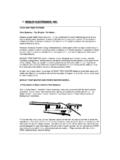
1 CHECKING TRAPSC hecking Mosley Antenna the wishes an Amateur Radio Operator has for his/her Antenna system is that it workforever without repair. Mosley antennas are well designed, but, as with all electro-mechanisms,failures do occur. When they do occur, the trouble must be located and repairs made as soon aspossible. It is hoped that the test procedures set forward here will help you maintain and repairyour Mosley trap-type Antenna system . The procedures described will apply to any Mosley dipole, beam, or vertical Antenna trap Antenna consists of a series of 1/4 wave elements. In the case of a verticalantenna, there is basically only one 1/4 wave element.
2 In the case of a dipole or beam, there aretwo 1/4 wave elements joined together to make a 1/2 wave vertical, beam, or dipole, the 1/4 wave element may be effectively broken at predeterminedintervals. This may be done with insulators, by terminating the tubing, or by installing parallelresonant circuits. Only in the last case can you construct anantenna system that willautomatically change bands. In Mosley Antenna Systems these resonant circuits are called"Trap Assemblies". These highly efficient assemblies usually have two parallel resonant circuitswithin them. The resonant circuit operating on the highest frequency, Mhz. is nearest thebase of the vertical.
3 In the case of a dipole or beam, it is nearest the Antenna center or closest tothe boom In the opposite end of this assembly another resonant circuit is found that operates onthe next lowest frequency. This circuit usually works at about Mhz. Individual TRAPS cannot bechecked by a grid-dip to the circuitry of trap-type antennas, it will be found that any malfunction of the antennasystem on the highest resonantfrequency will also cause the Antenna system to operateincorrectly on the lower resonant frequencies. It is possible that the highest frequency portion ofthe Antenna may work properly and the lower frequencies may not work properly.
4 In very rarecases,we find that only the two highest resonant frequencies will work properly and the lowestresonant frequency will not work very good check of the Antenna is to check the standing-wave-ratio on all the bands on whichthe Antenna is designed to operate. This check should be done every 100 kcs. in and out of theband. A malfunction on any of the bands will be indicated by higher than normal SWR CHECKING SWR, be sure of the accuracy of your measuring instrument and that the properconnection is used. Nothing should be installed between the SWR instrument and the antennasexcept the connecting transmission line. Filters, relays etc.
5 May cause incorrect readings wheninstalled between the SWR bridge and the Antenna . Be sure the transmitter is operating on thecorrect frequency and no serious harmonics are present. When you are making these tests, uselow power. Some SWR instruments do not indicate minimum SWR at the true cases where a high SWR is indicated on all bands of operation, and if all components, otherthan the Antenna , are known to be functioning correctly, check all the following:Transmission line and its connections. Check the overall Antenna lengths up to the the highestfrequency resonant circuit, which is the portion of the trap assembly nearest to boom on a beamor dipole or the portion of the vertical nearest the the cases where a high SWR is obtained on the lower resonant frequencies and a normal SWRis obtained on the highest resonantfrequency, the indications are that something is wrong withthe outer resonant circuit.
6 This portion of the trap assembly is located on the outboard ends of theantenna, furthest from the center on a beam or dipole or furthest above ground on a the rare cases where only the lowest frequency of a tri-band element is operating incorrectly, itis advisable that the element lengths be checked. This length would consist of the element fromthe outboard end of the trap assembly to the tip of the Antenna vertical Antenna Systems , it is possible that more than one trap assembly will be used. Thiscould also be true of beams and dipoles. These Systems incorporate even lower frequencyresonant circuits. These TRAPS may not necessarily be inthe same assembly as noted for thehigher resonant frequencies.
7 Use of the TRAPS is the same and defective assemblies may belocated by noting at what band a high SWR is first located. The frequency band at which the highSWR is first located (going fromhighest band to lowest band) indicates that the defectivecomponent is used on this band and is affecting the lower assemblies can be visually inspected. Before disassembly, not that the color coding is stillon all components or devise some method to insure reassembly of the trap onto the Antenna inthe correct have been asked frequently by BEAM users how to correctly install the TRAPS when the colorcoding has weathered off. The following system of color coding is used on all trap assembliesused on BEAMS:Both coils used to make on trap assembly are color coded with the SAME color.
8 On the coil,which is placed closest to the boom, the code will appear on the tubing and will be visible whenthe plastic trap seals are the JUNIOR series of beams, the outboard coil is coded on the short end of the tubingextending beyond the coil form. To inspect for this code, it is necessary to remove the coils fromthe trap the SENIOR series of beams, the outboard coil is color coded on the plastic coil form. It is notnecessary to remove this coil for inspection. This color code will be covered by the trap outboard color code is not used for assembly when assembly is performed as stated in theassembly disassemble the trap assembly, begin by pulling the trap seals from the ends of the trapassemblies.
9 These seals can be removed without damaging them. The removal of these sealswill expose a wire which is terminated to the end of the outsidemetal cover. Remove the outerscrew terminating this wire. Place one hand on the cover, or largest tube. Place the other handaround the small tubing and the thumb of this hand on the wire. Pull the assembly apart using thethumb to keep the wire from unwinding or loosing any tension. Tape this unterminated wire to theplastic coil from and inspect the coil form. Damage may be noted by shorted turns, deformed coilforms, melted plastic form and other abnormalities. It is important that these coils have thecorrectnumber of turns.
10 The instructions pertinent to the Antenna being inspected usually give theseturns and overall Antenna reassembling the Antenna , note that the wire on each coil form is tight because loose wireswill detune these coils and cause additional troubles. Be sure screw is pulled down tightly andwire and screw are clean.
