Transcription of Chilled Water Fan Coil Unit - Trane
1 Chilled Water FanCoil UnitModel: HFCF02~HFCF14 Airflow Range: 200~2400m3/h The Best Results- Quiet Comfort Low noise permanent split capacitor motor. Metal fan wheel both statically and dynamically balanced. Threaded connection, match up duct collars and keyholes for hangers shorten installation time. Quick delivery helps meet tight installation Latest Perfection Cleaner, quieter and more efficient fin design. The Best System- Design for comfort applications at home, office and shop. HFCF is easily installed in a false ceiling or closet, HFCF is the ideal solution for new or replacement applications. The Best Fit- Nine sizes to meet capacity requirements - One unit provides total comfort requirements: both cooling and heating- Low height of just 230mm on all sizes means no difficulty in fitting tight ceiling applications Flexibility- Easy to change Water hand connections on the field. ReliabilityTrane s history of innovation and technology leadership led to quality products making Trane a leader in the air conditioning markets worldwide.
2 Trane s commitment to customer s needs for quality, efficiency and reliability is evident from the largest chiller to smallest fan and Benefits2 LCD Thermostat (except for DCBL) TDG/Control OptionsWater Control ValveZN510/520 (for Trane ICS) Zone Sensor (for Trane ICS) HFCF AccessoriesThe Best Choice for ComfortFanFilter (Option)MotorPlenum (Option)Junction boxDrain panDrain pan purgeCoil head supportAir ventCoilElectric heater (Option)Model Nomenclatures3 Digit 1: H = Horizontal Digit 2: F = Fan Coil Digit 3: C = Concealed TypeDigit 4: F = Design SequenceDigit 5, 6: Size / Nominal Airflow 02 = 200 CFM 03 = 300 CFM 04 = 400 CFM 05 = 500 CFM 06 = 600 CFM 08 = 800 CFM 10 = 1000 CFM 12 = 1200 CFM 14 = 1400 CFM Digit 7: Connection Side L = Left Connection R = Right Connection Digit 8: Coil Rows 2 = 2 Rows Cooling 3 = 3 Rows Cooling 4 = 4 Rows Cooling A = 2 Rows Cooling, 1 Row Heating B = 3 Rows Cooling, 1 Row Heating Digit 9: Electric Heater (Size) N = None A = kW Heater (02) B = kW Heater (03) C = kW Heater (04) D = kW Heater (05) E = kW Heater (06) F = kW Heater (08) G = kW Heater (10) H = kW Heater (12) J = kW Heater (14) Digit 10: Motor Type N = Normal H = High Static A = DCBL Normal w/ LCD Thermostat B = DCBL High Static w/ LCD Thermostat C = Hermetic Motor Normal Type D = Hermetic Motor High Static Type Digit 11: Voltage/Hz/Phase 1 = 220/50/1 2 = 220~240/60/1 3 = 115/60/1 Digit 12.
3 Factory Mounted Control / Valve Package N = None A = 2-pipe, with 2-way Valve B = 2-pipe, with 3-way Valve C = 4-pipe, with 2-way Valves D = 2-pipe, with 2-way Valve & LCD Thermostat E = 2-pipe, with 2-way Valve & LCD Thermostat (Configured with VWV System only) F = 2-pipe, with 3-way Valve & LCD Thermostat G = 4-pipe, with 2-way Valves & LCD Thermostat H = 2-pipe, with 2-way Valve & ZN510 w/ Zone Sensor J = 2-pipe, with 3-way Valve & ZN510 w/ Zone Sensor K = 4-pipe, with 2-way Valves & ZN510 w/ Zone Sensor L = 2-pipe, with 2-way Valve & ZN520 w/ Zone Sensor M = 2-pipe, with 3-way Valve & ZN520 w/ Zone Sensor P = 4-pipe, with 2-way Valves & ZN520 w/ Zone Sensor Q = 2-pipe, with 2-way Floating Valve & ZN520 w/ Zone Sensor R = 2-pipe, with 3-way Floating Valve & ZN520 w/ Zone Sensor S = 4-pipe, with 2-way Floating Valves & ZN520 w/ Zone SensorDigit 13: Terminal Box A = Standard Wiring w/ Terminal Box B = Electric Heater Wiring w/ Terminal Box C = DCBL Wiring w/ Terminal Box D = ZN Wiring w/ Terminal Box E = VWV w/ Terminal BoxDigit 14: Return Plenum / Filter N = None A = with Rear Plenum Only B = with Rear Plenum/ 6mm Nylon Filter C = with Rear Plenum/ 20mm Aluminum Filter D = with Bottom Return Plenum Only E = with Bottom Return Plenum/ 6mm Nylon Filter F = with Bottom Return Plenum/ 20mm Aluminum FilterDigit 15: Drain Pan A = STD.
4 Galvanized Steel w/ 7mm PE Insulation B = STD. Galvanized Steel w/ 7mm PE Insulation & Extended 200mm C = STD. Galvanized Steel w/ 7mm PE Insulation & Extended 310mm D = Stainless Steel w/ 7mm PE Insulation E = Stainless Steel w/ 7mm PE Insulation & Extended 200mm F = Stainless Steel w/ 7mm PE Insulation & Extended 310mm G = STD. Galvanized Steel w/ 6mm Non-flammable Close Cell Insulation H = STD. Galvanized Steel w/ 6mm Non-flammable Close Cell Insulation & Extended 200mm J = STD. Galvanized Steel w/ 6mm Non-flammable Close Cell Insulation & Extended 310mm K = Stainless Steel w/ 6mm Non-flammable Close Cell Insulation L = Stainless Steel w/ 6mm Non-flammable Close Cell Insulation & Extended 200mm M = Stainless Steel w/ 6mm Non-flammable Close Cell Insulation & Extended 310mm N = STD. Galvanized Steel w/ 10mm Non-flammable Close Cell Insulation P = STD. Galvanized Steel w/ 10mm Non-flammable Close Cell Insulation & Extended 200mm Q = STD. Galvanized Steel w/ 10mm Non-flammable Close Cell Insulation & Extended 310mm R = Stainless Steel w/ 10mm Non-flammable Close Cell Insulation S = Stainless Steel w/ 10mm Non-flammable Close Cell Insulation & Extended 200mm T = Stainless Steel w/ 10mm Non-flammable Close Cell Insulation & Extended 310mm U = STD.
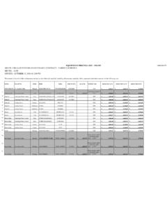
5 Galvanized Steel w/ 25mm Non-flammable Close Cell Insulation V = STD. Galvanized Steel w/ 25mm Non-flammable Close Cell Insulation & Extended 200mm W = STD. Galvanized Steel w/ 25mm Non-flammable Close Cell Insulation & Extended 310mm X = Stainless Steel w/ 25mm Non-flammable Close Cell Insulation Y = Stainless Steel w/ 25mm Non-flammable Close Cell Insulation & Extended 200mm Z = Stainless Steel w/ 25mm Non-flammable Close Cell Insulation & Extended 310mm Digit 16: Trane Digital Grille(TDG) N = None A = with Remote Controller Only B = with TDG LCD Thermostat Only C = with TDG LCD Thermostat & Remote Controller D = with Remote Controller & UV Light E = with TDG LCD Thermostat & UV Light F = with TDG LCD Thermostat, Remote Controller & UV LightDigit 17: Future Use N = NoneDigit 18: Region A = APR B = MAIR C = LARH F C F 0 3 L 3 N N 1 N A N A N N A_ _ _ _ _ _ _ _ _ _ _ _ _ _ _ _ _ _1 2 3 4 5 6 7 8 9 10 11 12 13 14 15 16 17 18 Performance Data4 Cooling Capacity (Example) Cooling Capacity: kW Cooling Rows : 3 SH: Sensible Cooling Capacity, kW EAT: 26 C/ Motor Frequency: 50Hz/ 60Hz WPD: Water Pressure Drop, kpa ESP: 12/50 Pa (Normal / Hi-Static) TH: Total Cooling Capacity, kW WFR.
6 Water Flow Rate, Input Power Model Nominal Entering Water Temperature Airflow WTR 5 C 7 C 9 C (CMH) ( C) SH TH WFR WPD SH TH WFR WPD SH TH WFR WPD 02 340 03 510 04 680 05 850 06 1020 08 1360 10 1700
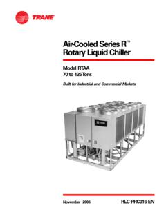
7 12 2040 14 2380 Model 02 03 04 05 06 08 10 12 14 Nominal Airfow(CMH) 340 510 680 850 1020 1360 1700 2040 2380 Input Power(Watt)* Hi-Static Motor 44 56 64 85 92 145 176 216 286 Normal Motor 23 29 43 67 77 117 142 173 195*Available with 115V/60Hz, 220V/50Hz, or 230V/60Hz Options*Heat Capacity Type( KW ) Hot Water 1 Row EWT=55 C; EAT=21 C; WFR= Electric Sheathed Element * Plenum / Filters Return air plenum with filters PP nylon or aluminumNote: Trane has right to reserve any changes without noticeDimension Data and Weight5 HFCF Standard UnitHFCF Bottom Return Plenum and FilterHFCF Rear Return Plenum and FilterNotes:1.
8 Dimension in Above shown with right hand coil connection. 3. Wiring connection is located at the same side as coil and drain Wiring and junction box will be supplied by Trane . Net Weight (kg) Net Weight (kg) without Plenum Box and Filter with Plenum Box and Filter unit Dimension (mm) Motor Fan Model Qty. Qty. Normal Static High Static Normal Static High Static A B C D 2 Row 3 Row 4 Row 2 Row 3 Row 4 Row 2 Row 3 Row 4 Row 2 Row 3 Row 4 Row HFCF02 458 485 648 547 1 1 12 13 14 13 14 15 15 16 17 16 17 18 HFCF03 693 720 883 782 1 2 16 18 20 17 19 21 20 22 24 21 24 25 HFCF04 793 820 983 882 1 2 17 19 21 18 20 22 21 23 25 22 25 26 HFCF05 913 940 1103 1002 1 2 19 21 23 20 22 24 24 26 28 24 28 28 HFCF06 963 990 1153 1052 1 2 20 22 24 21
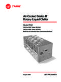
9 23 25 25 27 29 25 29 29 HFCF08 1243 1270 1433 1332 2 3 28 30 32 29 31 33 34 36 38 35 38 39 HFCF10 1493 1520 1683 1582 2 4 30 33 36 32 35 38 37 40 43 39 43 45 HFCF12 1663 1690 1853 1752 2 4 35 38 41 36 39 42 43 46 49 44 49 50 HFCF14 1793 1820 1983 1882 2 4 37 40 43 38 41 44 45 48 51 46 51 52 648746419211110145242701421112 A B C 2943 Centrifugal FanMotor216 230147 Four Hanger Holes See View ADrain connection 3/4" MPT Water Outlet 3/4"FPT Water Inlet 3/4" FPT AirOutletJunction BoxCoilDrain Pan 61111014524270142111243 A B C 29543520248248198 D 216 230188147 Six Hanger Holes See View ADrain connection 3/4" MPT Water Outlet 3/4"FPT Water Inlet 3/4" FPTB ottom ReturnPlenum BoxCentrifugal FanMotorReturn PlenumFilterJunction BoxCoilDrain Pan 65224991111014524270142111243 A B C29243198226 DSix Hanger Holes See View ADrain connection 3/4" MPT Water Outlet 3/4"FPT Water Inlet 3/4" FPTCoil 216 230 AirOutletRear ReturnPlenum BoxDrain PanCentrifugal FanMotorReturn PlenumFilter188147 Junction Box 11 18 14 View A AirOutletSound Pressure Data/Wiring Diagram/Coil Connection 6 Motor Type Normal Hi-Static unit Octave Band (dB) & Center Frequency (Hz) Octave Band (dB) & Center Frequency (Hz)
10 Model Speed 63 125 250 500 1000 2000 4000 8000 63 125 250 500 1000 2000 4000 8000 High 20 15 25 27 31 29 17 10 19 24 28 33 37 37 25 13 02 Med 20 14 19 23 23 19 11 9 19 22 26 31 34 33 21 11 Low 19 13 15 19 21 11 11 9 19 15 17 23 24 22 12 9 High 12 12 21 28 28 24 14 11 16 24 28 35 38 37 27 13 03 Med 10 8 13 19 18 14 13 11 11 19 22 29 31 29 17 9 Low 13 4 6 15 16 11 12 11 6 13 14 22 23 18 11 9 High 16 17 25 31 33 32 18 9 15 26 33 38 41 39 28 15 04 Med 17 16 18 25 25 21 11 9 17 21 25 32 34 31 19 10 Low 17 16 15 19 19 11 10 8 13 12 16 23 24 17 11 9 High 18 19 34 35 37 37 25 12 14 29 33 39 42 41 31 19 05 Med 20 17 27 31 33 30 18 12 12 23 29 33 36 34 23 11 Low 29 24 28 31 32 27 24 21 12 16 20 27 28 22 13 9 High 17 19 32 36 39 38 27 14 17 31 34 39 43 42 33 20 06 Med 19 14 22 28 29 26 15 9 21 26 30 35 38 37 26 13 Low 17 11 14 22 22 14 10 9 14 19 23 30 31 26 16 10 High 19 23 32 37 39 41 31 16 18 32 36 41 45 46 38 25 08 Med 26 20 28 32 33 34 21 10 17 27 31 37 41 41 31 18 Low 19 18 25 27 28