Transcription of Chilled-Water System Decisions - Trane
1 2018 Trane . All rights reserved. 1 Engineers Newsletterproviding insights for today s hvac System designervolume 47 3impacts of Chilled-Water System Design DecisionsThis Engineers Newsletter walks through a number of design Decisions , with discussion and examples to explain how and why those Decisions are made. While designing a Chilled-Water System , a myriad of Decisions must be made. Experienced engineers often make these Decisions "automatically" as they have in the past, based on what they have learned from experience. Today, all engineers likely use an internet search engine to get direction, but when there are differing or even conflicting recommendations a decision must be Decisions regarding Chilled-Water System designs include: bypass line sizing in variable flow systems dynamically varying condenser water flow number of Chilled-Water pumps to operate series chillers and power consumption whether to use pressure -independent control valvesPrimary-secondary System bypass sizing.
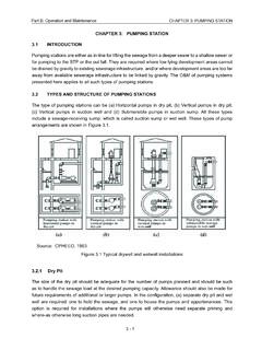
2 The premise of a primary-secondary System is to hydraulically separate (decouple) the primary (chiller) flow from the secondary ( System ) flow. This decoupling prevents the operating pressures of chiller pumps from impacting the operating pressures of the System pumps. This is accomplished by installing a bypass line with a small pressure drop. The bypass allows water to flow in either direction and is used to indicate chiller and primary pump sequencing in this System arrangement (Figure 1).Chillers and constant flow primary pumps are enabled in pairs, making the primary flow rate a step function. As System load and flow increase, the excess flow rate (from supply to return) in the bypass line decreases. At the point that System flow rate exceeds chiller flow rate, deficit flow Bypass line sizingThis seemingly simple decision can have significant consequences if not done correctly.
3 In a primary-secondary System , the bypass pipe should be the same diameter as the pipe going into the largest chiller. Its length should be about 8-10 pipe diameters long or have an equivalent pressure drop. In a variable primary flow (VPF) System , the bypass line should be sized for the largest minimum flow rate and it will have a control reasons behind this guidance follow. Figure 1. Primary-secondary systembypass line, free of restrictions, sized the same as the largest chiller s pipe, aim for a pressure drop equivalent to a pipe that is 8-10 pipe diameters pumps with VSDsprimary pumpschilled- water coling coils with two-way valves 2 Trane Engineers Newsletter volume 47-3providing insights for today s HVAC System designer(from return to supply) in the bypass line occurs.
4 This warm, deficit water flow increases the System supply- water temperature and at some point an additional chiller and primary pump are chiller and pump are disabled when excess flow rate in the bypass line is high enough to still have excess flow after a primary pump is turned off. Therefore the maximum flow rate the bypass line ever experiences is a little higher than the design flow rate of the largest chiller. Often designers wait for 10-15 percent excess flow, to ensure that chillers are not cycled on and off rapidly. Therefore the bypass pipe should be sized for 110 to115 percent of the largest chiller's flow rate which most designers simplify to the same as the pipe size going into the largest happens if bypass sizing is not right? Too little or too much pressure can cause small, pressure too high? An undersized bypass line can result in high fluid velocity, which in extreme conditions may cause pipe erosion, vibration and acoustic issues.
5 The high fluid velocity can also result in high enough pressure drop so that flow is restricted through the bypass, and may actually cause the primary and secondary pump pressures and flow rates to affect each large, pressure too low? A benefit of an oversized bypass pipe is a very low pressure drop, however if it's too low, the water may not flow as intended. Figure 2 illustrates the issue: Cold water leaves the chillers and flows into the chiller supply manifold. A portion of that cold water flows toward the secondary pump. However due to the very low pressure drop in the bypass, some of the cold water seeks the path of least resistance and flows through the bypass line in the excess direction. Similarily in the return- water side, warm return water flows in the System return return watersystem return waterchiller supply watersystem supply watershort-circuited chiller supply watershort-circuited System return waterFigure 2.
6 Oversized bypass can allow simultaneous flow in both directions Much of that water continues to the chillers but some of the warm water (due to low pressure drop in the bypass) flows in the deficit direction in the bypass line (from return to the supply).As a result there is simultaneous flow in opposite directions because the bypass line has become so large it functions like a tank!The diluted (higher) System supply- water temperature results in more pumping energy. The short-circuited supply water mixing with return water results in reduced chiller return- water temperature. This can restrict the chillers ability to fully the pipes are already installed how can the situation be improved? A resolution for too low of a pressure drop is to impose a modest restriction to keep water from short-circuiting. Aim for the equivalent pressure drop of a pipe that is 8 to 10 pipe diameters long.
7 Often the first solution considered is to add a valve. Given that the bypass line is oversized, it s likely the additional valve will be big and expensive. It s also likely that at some point a well-meaning but uninformed operator will close the valve too much. Or, they might open it all the way and defeat this solution. Recall that the bypass line in a primary-secondary System should allow water to flow freely, in either direction, as pressure drop. A better option may be to place an orifice in the line. This can simply be a plate with a hole in it. This imposes a pressure drop, but allows water to flow freely in either the surplus or deficit direction. In a few extreme cases it has been neccessary to completely block off the oversized/short bypass pipe and install a properly sized pipe of sufficient length to eliminate the mixing best way to avoid issues in a primary-secondary System is to size the bypass line properly during the design process.
8 Simply check the drawings and ensure that the bypass line is smaller than the manifold, and the same size as the pipe going into the largest chiller and 8 to 10 equivalent pipe diameters long. If the pipe is less than 8 to10 pipe diameters long, using elbows to form a "U" adds an appropriate pressure System bypass line sizing. Conceptually a variable- primary-flow System is simpler to get right. The valve in the bypass line only opens when the System flow rate approaches the minimum flow rate of the operating chiller(s). So the bypass pipe and valve only need to be sized for the largest minimum flow rate. Usually that's the largest chiller's minimum flow rate. However, depending on chiller selections, the largest minimum flow rate might not be for the largest chiller in the plant. Also consider the combined minimum flow required when two chillers are operating at part load, just before sequencing off one insights for today s HVAC System designerTrane Engineers Newsletter volume 47 3 3 Should we dynamically vary the condenser water flow?
9 Yes, savings are available in existing systems designed between to gpm/ton (12 to F T) condenser water flow rate. Controls complexity should be accounted for and the System needs to be properly , in new systems designed for to gpm/ton ( to F T) condenser water flow rate since they already achieve almost all the savings and reduce System complexity a lot. Systems designed at these flow rates do not require varying the condenser water flow rate. Why? Varying condenser water flow rate can be complicated. There are several limit conditions and setpoints to manage: The flow rate has to stay above the minimum flow rate as defined by the highest of minimum tower flow, minimum chiller flow, or to produce the static lift in the open portion of the condenser water System . When any of these are close to the System design flow, variable flow should not be attempted.
10 At each operating point during the year, determine the optimal condenser water pump and cooling tower speed. Make sure not to reduce the condenser flow at conditions and operating points that cause the chiller to surge. Ensure the sequence is documented and properly complexity requires that the System be commissioned, the controls remain operational and future changes are accommodated. Careful consideration should be made for System changes such as chiller, pump, and/or tower replacements. Pumps are smaller with significantly lower power Chiller power rises marginally Cooling towers become more effective as heat exchangers, since warmer water is sent to the cooling tower, resulting in Reduced tower fan power Reduced tower cost Possible reduction of tower size (which further reduces tower cost).Observations. In all cases the operating savings (Table 1) are very similar, so what guidance can be provided?