Transcription of Chiller Plant Design - Olympic International
1 Application GuideAG 31-003-1 2002 McQuay InternationalChiller Plant DesignElevation DifferenceColumn HeightWhen Pump Is OffBuilding Load600 Tons(50% Load) Secondary Pump1440 gpm480 gpm Flow ThroughDecouplerFlow Two 400 Ton ChillersEach At 300 Tons(Balanced Load) Return WaterTo ChillerChiller 1- OnChiller 2- OnChiller 3- Off44F44F54F Two Primary Pumps Each At 960 Guide AG 31-003-1 Table of ContentsIntroduction .. 4 Using This 4 Basic System .. 4 Chiller 4 Piping basics .. 7 Pumping basics .. 11 cooling Tower 15 Load basics .. 20 Control Valve basics .. 20 Loop Control basics .. 23 Piping 24 Water Temperatures and Ranges .. 25 Supply Air 25 Chilled Water Temperature Range .. 26 Condenser Water Temperature Range Trends .. 27 Air and Evaporatively Cooled Chillers.
2 28 Air-Cooled Chillers .. 28 Evaporatively Cooled 30 Dual Compressor and VFD Chillers .. 31 Dual Compressor 31 VFD Chillers .. 31 System Design 32 Mechanical Room Safety .. 34 Standard 34 Standard 34 Single Chiller System .. 38 Basic Operation .. 38 Basic Components .. 38 Single Chiller Sequence of 39 Parallel Chiller System .. 41 Basic Operation .. 41 Basic Components .. 41 Parallel Chiller Sequence of Operation .. 42 Series Chillers .. 44 Basic Operation .. 44 Basic Components .. 44 Series Chillers Sequence of Operation .. 46 Series Counterflow 47 Using VFD Chillers in Series Arrangements .. 49 System Comparison .. 49 Primary/Secondary Systems .. 51 Application Guide AG 31-003-13 Basic Operation .. 51 Basic Components .. 51 Very Large Chiller plants .
3 58 Primary/Secondary Sequence of Operation .. 58 Water-Side Free cooling .. 61 Direct Waterside Free 61 Parallel Waterside Free cooling .. 61 Series Waterside Free cooling .. 62 Waterside Free cooling Design Approach .. 63 cooling Tower Sizing .. 63 Waterside Free cooling Sequence of Operation .. 64 Economizers and Energy Efficiency .. 65 Hybrid plants .. 66 Heat Recovery and Templifiers .. 67 Load 67 Heat Recovery Chillers .. 67 Templifiers .. 71 ASHRAE Standard .. 73 Variable Primary Flow Design .. 75 Basic Operation .. 75 Basic Components .. 75 Variable Primary Flow Sequence of 76 Training and Commissioning .. 78 Low Delta T Syndrome .. 80 Low Delta T Example .. 80 Low Delta T Syndrome Causes and Solutions .. 82 Other Solutions .. 84 Process Applications.
4 86 Process Load Profiles .. 86 Condenser 87 Winter Design .. 87 Chilled Water Volume .. 87 Temperatures and Ranges .. 88 Minimum Chilled Water Volume .. 89 Estimating System Volume .. 89 Evaluating System Volume .. 89 Conclusions .. 92 References .. 93 The information contained within this document represents the opinions and suggestions ofMcQuay International . Equipment, the application of the equipment, and the systemsuggestions are offered by McQuay International as suggestions only, and McQuayInternational does not assume responsibility for the performance of any system as a result ofthese suggestions. Final responsibility for the system Design and performance lies with thesystem Guide AG 31-003-1 IntroductionUsing chilled water to cool a building or process is efficient and flexible.
5 A two-inch Schedule 40pipe of chilled water can supply as much comfort cooling as 42" diameter round air duct. The use ofchillers allows the Design engineer to produce chilled water in a central building location or even onthe roof and distribute the water economically and without the use of large duct shafts. Chilled wateralso provides accurate temperature control that is especially useful for variable air volume (VAV) purpose of this manual is to discuss various piping and control strategies commonly used withchilled water systems including variable flow pumping This GuideThis Guide initially discusses the components used in a chilled watersystem. It then reviews various Chiller Plant designs explaining theiroperation, strengths and weaknesses.
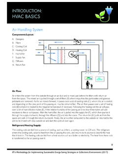
6 Where appropriate, sequence ofoperations are provided. Each project is unique so these sequences arejust addition, many sections reference ASHRAE Standard TheASHRAE section numbers are provided in parentheses to direct thereader. The sections referenced in this Guide are by no means is recommended that the reader have access to a copy of Standard well as the Users Manual. The Standard and manual can be purchasedonline at System Figure 1 shows a basic Chiller loop with a water-cooled Chiller . The system consists of a Chiller , cooling tower, building cooling load, chilled water and condensing water pumps and piping. Thissection will review each of the 1 - Single Chiller LoopChiller BasicsThe Chiller can be water-cooled, air-cooled or evaporatively cooled.
7 The compressor types typicallyare reciprocating, scroll, screw or centrifugal. The evaporator can be remote from the condensingsection on air-cooled units. Thishas the advantage of allowing thechilled water loop to remain insidethe building envelope when usingan outdoor Chiller . In applicationswhere freezing conditions can beexpected, keeping the chilled waterloop inside the building avoids theneed for some form of can be multiple chillers in achilled water Plant . The details ofvarious multiple Chiller plantdesigns will be discussed in Water LoopCooling TowerBuilding LoadChilled Water LoopChillerChilled Water PumpCondenser Water PumpApplication Guide AG 31-003-15 The chilled water flows through the evaporator of the Chiller .
8 The evaporator is a heat exchangerwhere the chilled water gives up its sensible heat (the water temperature drops) and transfers the heatto the refrigerant as latent energy (the refrigerant evaporates or boils).Flow and Capacity CalculationsFor air conditioning applications, the common Design conditions are 44 F supply water temperatureand gpm/ton. The temperature change in the fluid for either the condenser or the evaporator canbe described using the following formula:Q = W x C x TWhereQ = Quantity of heat exchanged (Btu/hr)W = flow rate of fluid (USgpm)C = specific heat of fluid (Btu/lb F) T = temperature change of fluid ( F )Assuming the fluid is water, the formula takes the more common form of:Load (Btu/hr) = Flow (USgpm) x ( Fin Fout) x 500 OrLoad (tons) = Flow (USgpm) x ( Fin Fout)/24 Using this equation and the above Design conditions, the temperature change in the evaporator isfound to be 10 F.
9 The water temperature entering the evaporator is then 54 air conditioning Design conditions are based on 75 F and 50% relative humidity (RH) in theoccupied space. The dewpoint for air at this condition is F. Most HVAC designs are based oncooling the air to this dewpoint to maintain the proper RH in the space. Using a 10 F approach at thecooling coil means the supply chilled water needs to be around 44 F or 45 designer is not tied to these typical Design conditions. In fact, more energy efficient solutions canbe found by modifying the Design conditions, as the project the chilled water flow rate affects a specific Chiller 's performance. Too low a flow ratelowers the Chiller efficiency and ultimately leads to laminar flow.
10 The minimum flow rate is typicallyaround 3 fps (feet per second). Too high a flow rate leads to vibration, noise and tube erosion. Themaximum flow rate is typically around 12 fps. The chilled water flow rate should be maintainedbetween these limits of 3 to 12 condenser water flows through the condenser of the Chiller . The condenser is also a heatexchanger. In this case the heat absorbed from the building, plus the work of compression, leaves therefrigerant (condensing the refrigerant) and enters the condenser water (raising its temperature). Thecondenser has the same limitations to flow change as the and Energy EfficiencyChillers are often the single largest electricity users in a building. A 1000 ton Chiller has a motorrated at 700 hp.