Transcription of Choked Flow of Gases
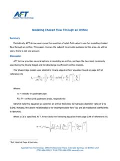
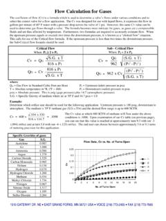
1 38. Choked Flow of Gases TUTORIAL. The Basic Concept When the air velocity reaches sonic velocity The reason for the mass flow rate limitation is A greatly misunderstood and misapplied (P2 /P1 .528) further increases in P1 (upstream the fixed inlet density combined with the fixed notion is that of Choked flow , also referred pressure) do not cause any further increase in velocity. The flow charts on pages 16-18 show to as critical flow . the air velocity through the orifice. Conse- the Choked mass flow effect for vacuum con- quently it is wrongly concluded that the mass ditions. At vacuum levels between 15-30 Hg In gas flow through an orifice there is an occa- flow rate also does not increase. the mass flow rate is fixed. sion where the gas velocity reaches sonic conditions. This occurs for air flow when the As the air pressure (P1) increases, the density Choked Flow for Positive absolute pressure ratio is .528, when the of the air also increases; and since the mass downstream absolute pressure (P2) is flow rate is also a function of density, the mass Pressure Conditions of the upstream absolute pressure (P1).
2 Flow rate increases linearly with pressure (P1). As in the case of the above vacuum conditions Mass Flow there are certain situations in which Choked Rate flow does occur for positive (above atmo- .. Mass Air Flow Rate Sonic Velocity Velocity P1 P2 spheric) pressure. By maintaining a fixed in- let pressure to the orifice and allowing the P2 = psia = 0 psig outlet pressure (back pressure) to vary, there Sonic velocity occurs for air flow when Air Velocity 0 is a range of outlet pressures over which the P2 /P1 .528. 0. 1 .528 0. mass flow rate is fixed. P2 /P1 Absolute Pressure Ratio . Air 1129 ft/sec Velocity Sonic Velocity 68 F For example (see chart below). Even though the air velocity through the orifice is limited Air velocity is to the speed of sound, the mass flow rate continues to With an inlet pressure of 80 psig, the mass constant in increase as the absolute pressure (P1) increases. flow rate is Choked (limited) for all outlet this region 0.
3 Pressures less than psig (including 1 .528. P2 /P1 Absolute Pressure Ratio 0. What is Choked ? vacuum conditions). The air flow velocity is limited once the absolute The parameter that becomes Choked or pressure ratio is .528. The actual flow rate is constant for the limited is the velocity of the air. It is more outlet pressure range of psig to as accurate to use the term Choked velocity . For air flow through an orifice with an low as a complete vacuum. The flow rate rather than Choked flow when the absolute inlet air temperature of 68oF the Choked can be obtained from the charts on pages pressure ratio of air through an orifice is (sonic) velocity is 1129 ft/sec. 16-18; for an orifice of .010" diam- .528. eter and with 80 psig inlet pressure, the The Misconception! Vacuum Conditions Choked flow rate is scfh (page 16). This Once sonic velocity is achieved in orifice air flow rate will be constant for all outlet flow (P2 /P1 =.)
4 528), it is easy to "assume" that pressure conditions between psig the mass flow rate is constant for all pressure and full vacuum. P1 = psia ratios less than .528; P2 /P1 .528. For = 0 psig P2 < P1. Vacuum example, when P2 is psia and P1 is Standard Atmospheric psia, sonic velocity occurs through the orifice. Conditions Sonic Velocity Conditions Air Flow As P1 further increases there is no further Inlet Pressure Outlet Pressure Air at atmospheric pressure enters the orifice and flows For Sonic Velocity increase in the velocity of the air flowing to a downstream vacuum pump. Gage Absolute Absolute Gage through the orifice. Pressure Pressure Pressure Pressure In the case of vacuum conditions on the outlet of an orifice and where the inlet is at ambient psig psia psia psig atmospheric pressure, both the air velocity 100 P1 = psia P2 = psia 90 = psig = 0 psig and the mass flow rate become Choked 80 Sonic Velocity (limited) when sonic velocity is achieved 70 Through Orifice through the orifice.
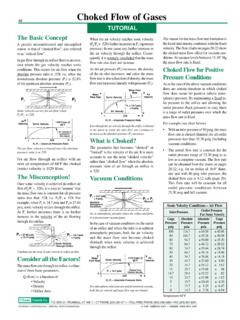
5 60 Conditions for the onset of sonic velocity in orifice air flow. 50 . 40 . Consider all the Factors! Mass Flow Rate Sonic Velocity 1129 ft/sec 68 F. Air Velocity 30 The mass flow rate through an orifice is a func- 20 tion of three basic parameters. P1 = psia Choked Flow 15 .98. 0. Choked Velocity .82..528 0. 1. Q (flow) is a function of 10 P2 /P1 Absolute Pressure Ratio Velocity 5 Density For atmospheric inlet pressure and downstream vacuum, 1 Orifice Area both the air velocity and mass flow rate are limited. 0 Temperature 68 F. BOX Q TRUMBULL, CT 06611 CT PHONE (203) 261-6711 TOLL FREE PHONE (800) 533-3285 FAX (203) 261-8331. O'KEEFE CONTROLS CO. 2000 ALL RIGHTS RESERVED e-mail website 16. Metal Orifice Air Flow SCFH. Orifice Diameter Inches Size Number 4 5 6 7 8 9 10 11 12 13 14 15 16 17 18 19 20 21 22 23 24 25 26 27 28 29 31 32 33. Cv 1 5 10 15 20 25 30 40 50 60 Supply Pressure psig 70 80 90 100 101. 5 10 15 In. Hg. 20 Vacuum Level Choked Flow 30 Orifice Diameter Inches Size Number 35 37 38 39 40 41 42 43 47 52 55 60 63 67 70 73 76 79 81 86 89 94 96 100 104 109 113 120 125.
6 Cv 1 101 106. 5 108 116 131 138 150 162 180 195 216 229. 10 103 112 121 131 144 153 172 181 196 216 237 250 286 314. 15 104 117 125 136 147 158 174 185 207 218 235 261 286 303 345 377. 20 106 123 138 146 160 172 185 203 216 242 256 275 305 335 354 403 445. 25 112 122 141 158 168 183 198 212 233 248 278 292 316 347 381 405 464 511. 30 107 126 138 160 179 190 206 222 239 265 280 314 331 356 392 432 458 525 578. 40 119 132 156 170 196 220 233 254 273 295 324 343 384 405 439 483 532 566 648 714. 50 112 142 157 185 202 233 261 278 301 324 347 384 407 456 481 523 576 634 672 771 850. 60 99 102 107 113 130 165 182 214 233 269 301 320 347 375 400 445 473 530 559 606 667 735 780 894 985. Supply Pressure psig 70 106 113 117 122 129 148 187 207 244 267 307 343 362 394 428 458 509 538 604 638 693 763 839 892 1021 1125. 80 93 103 110 119 127 131 137 145 167 210 231 273 298 343 384 405 443 481 513 570 604 678 716 778 856 943 1000 1146 1263.
7 90 106 115 122 132 141 146 151 161 185 231 256 303 331 379 424 447 489 532 568 631 670 750 792 860 947 1042 1106 1267 1398. 100 114 126 135 146 156 164 167 177 203 254 282 331 362 415 468 496 540 587 627 697 739 831 875 951 1047 1153 1225 1403 1545. 5 104 114 123 138 150. 10 106 110 120 130 142 153 173 187. 15 110 115 125 135 148 160 180 195. In. Hg. 20 110 115 125 135 148 160 180 195. Vacuum Level Choked Flow 30 110 115 125 135 148 160 180 195. Standard Conditions 70 F, psia SCFH Standard Cu. Ft. Per Hour Above data obtained with Type B restrictor. Flow rates for other metal restrictors are SLPM Standard Liters Per Minute essentially the same as for Type B. Above data supercedes previous publications. BOX Q TRUMBULL, CONNECTICUT 06611 CT PHONE (203) 261-6711 TOLL FREE PHONE (800) 533-3285 FAX (203) 261-8331. O'KEEFE CONTROLS CO. 2000 ALL RIGHTS RESERVED e-mail website Metal Orifice Air Flow SLPM. Orifice Diameter Inches Size Number 4 5 6 7 8 9 10 11 12 13 14 15 16 17 18 19 20 21 22 23 24 25 26 27 28 29 31 32 33.
8 Cv 1 5 10 15 20 25 30 40 50 60 Supply Pressure psig 70 80 90 100 5 10 15 In. Hg. 20 Vacuum Level Choked Flow 30 Orifice Diameter Inches Size Number 35 37 38 39 40 41 42 43 47 52 55 60 63 67 70 73 76 79 81 86 89 94 96 100 104 109 113 120 125. Cv 1 5 102 108. 10 102 112 118 135 148. 15 103 111 123 135 143 163 178. 20 102 114 121 130 144 158 167 190 210. 25 100 110 117 131 138 149 164 180 191 219 241. 30 105 113 125 132 148 156 168 185 204 216 248 273. 40 104 110 120 129 139 153 162 181 191 207 228 251 267 306 337. 50 110 123 131 142 153 164 181 192 215 227 247 272 299 317 364 401. 60 101 110 127 142 151 164 177 189 210 223 250 264 286 315 347 368 422 465. Supply Pressure psig 70 115 126 145 162 171 186 202 216 240 254 285 301 327 360 396 421 482 531. 80 109 129 141 162 181 191 209 227 242 269 285 320 338 367 404 445 472 541 596. 90 109 121 143 156 179 200 211 231 251 268 298 316 354 374 406 447 492 522 598 660. 100 120 133 156 171 196 221 234 255 277 296 329 349 392 413 449 494 544 578 662 729.
9 5 10 15 In. Hg. 20 Vacuum Level Choked Flow 30 Standard Conditions 70 F, psia SCFH Standard Cu. Ft. Per Hour Above data obtained with Type B restrictor. Flow rates for other metal restrictors are 17. SLPM Standard Liters Per Minute essentially the same as for Type B. Above data supercedes previous publications. BOX Q TRUMBULL, CONNECTICUT 06611 CT PHONE (203) 261-6711 TOLL FREE PHONE (800) 533-3285 FAX (203) 261-8331. O'KEEFE CONTROLS CO. 2000 ALL RIGHTS RESERVED e-mail website Sapphire Orifice Air Flow SLPM 18. Orifice Diameter Inches Size Number 3 4 5 6 7 8 9 10 11 12 13 14 15 16 17 18 20 22 24 26 28 30 32 34 36 40 44 48 52 54 58 64. Cv 1 5 10 15 20 25 30 40 50 60 Supply Pressure psig 70 80 90 100 5 10 15 In. Hg. 20 Vacuum Level Choked Flow 30 Sapphire Orifice Air Flow SCFH. Orifice Diameter Inches Size Number 3 4 5 6 7 8 9 10 11 12 13 14 15 16 17 18 20 22 24 26 28 30 32 34 36 40 44 48 52 54 58 64. Cv 1 5 10 15 20 25 30 40 50 60 Supply Pressure psig 70 80 90 100 5 10 15 In.
10 Hg. 20 Vacuum Level Choked Flow 30 Standard Conditions 70 F, psia SCFH Standard Cu. Ft. Per Hour Above data obtained with Type S restrictor. Flow rates for Type A, BTF, BWF, F, J, SLPM Standard Liters Per Minute L, P, and SF restrictors are essentially the same as for Type S. Above data supercedes previous publications. BOX Q TRUMBULL, CONNECTICUT 06611 CT PHONE (203) 261-6711 TOLL FREE PHONE (800) 533-3285 FAX (203) 261-8331. O'KEEFE CONTROLS CO. 2000 ALL RIGHTS RESERVED e-mail websit