Transcription of Chromalox Three Phase Equations and Heater Wiring …
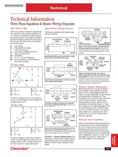
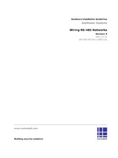
1 Chromalox Technical Documents Technical Technical Information Three Phase Equations & Heater Wiring Diagrams Open Delta & Wye Typical Heater Wiring Diagrams Contactor Heater (s). Three Phase heating circuits are most efficient The following diagrams show typical Heater L3. when operated under balanced conditions. If L2. Wiring schematics. L1. it is necessary to operate an unbalanced load, Sensor the Equations below can be used to calculate Fused T/C or RTD. Disconnect the circuit values for open Three Phase Delta or Fused Disconnect SPST Switches Wye circuits. The terms used in the Equations Switch Thermostat 1or 3 Electronic are identified below: Phase power Source Temperature Control L1. VL = Line Voltage 1 Phase Single or Three Phase AC Heater circuit using electronic VP = Phase (Element) Voltage power temperature controllers and contactors. Controller and IL = Line Current (Amps) Source contactor holding coil must be rated for the same voltage ILL = Line Current (Unbalanced Phase ) L2 as the Heater circuit.
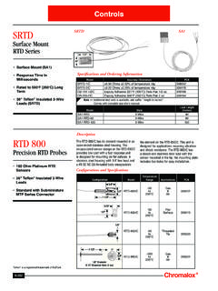
2 Control circuit requires over- current Heater (s) protection. IP = Phase Current (Amps). WT = Total Watts Single Phase 120 VAC Heater circuit where line voltage High Speed R1 = R2 = R3 = Element Resistance Circuit SCR power and current do not exceed thermostat rating. Fuses Breaker Controller Rc = Circuit Resistance in Ohms Measured 1 or 3. from Phase to Phase Phase L3 Heater (s). power L2. DPST. 3 Open Delta Thermostat Source L1 Sensor T/C. or RTD. Electronic 1 Phase L1 Temperature IL power Control Source L2. R1 Single or Three Phase AC Heater circuit using an VP electronic temperature controller and a SCR (solid state). VL Fused Disconnect Heater (s). IP Switch power controller. Controller must be rated the same voltage as the Heater circuit. Control circuit requires over-current Single Phase AC circuits where line voltage and current protection. All electrical Wiring to electric heaters must be do not exceed thermostat rating. installed in accordance with the National Electrical Code or R2 local electrical codes by a qualified person.
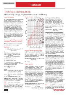
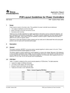
3 ILL. Wiring & Ambient Temperatures VP = VL VL = VP L3 Ambient temperatures must be considered 3 Phase WT = 2VL x IL WT = 2 (VL2 R1) when selecting Wiring materials for electric power L2. IP = IL IL = IP Source Heater circuits. Heating equipment and pro- L1 cesses may cause associated Wiring to operate WC = 2VP x IP ILL = X IP. Fused DPST Ther- Heater (s) well above ambient temperatures. These The loss of a Phase or failure of an element in Disconnect mostat temperatures may result from heat conducted a Three (3) element Delta circuit will reduce the Switch from the Heater terminals, radiation from wattage output by 33%. heated surfaces or simply high ambient air Three Phase AC Heater circuit where line voltage and temperatures. Nickel plated copper or nickel 3 Open Wye current do not exceed thermostat rating. Circuit does not alloy conductors with high temperature insula- have a positive off. tion should always be used in high tempera- ture areas. Outside these areas, conventional VP Fused Disconnect Wiring materials can usually be used.
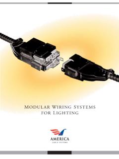
4 60 C. IP Switch Contactor R2 building wire is usually not suitable unless L3. 1 or 3 L2 otherwise indicated. VL Phase L1. R1. power Source Heater (s). Wiring in Severe Conditions L1. L2 Moist or wet locations require gasketed termi- DPST. IL Thermostat nal and junction boxes to protect equipment and Wiring . Rigid conduit is recommended. Single or Three Phase AC Heater circuit where line volt- VP = VL 2 VL = VP X 2 Hazardous Locations require the use of ap- age and current exceed thermostat rating. Separate con- WT = IL x VL WT = VL2 2R1 trol circuit can use a single pole or double pole thermostat. proved explosion-proof terminal and junction IP = IL IL = IP Control circuit requires over-current protection. boxes. Rigid conduit or mineral insulated (MI). RC = VL2 WC cable is mandatory in Division 1 areas. Some INFORMATION. WARNING Hazard of Electric Shock. Any Hazardous Locations may require conduit TECHNICAL. The loss of a Phase or failure of an element in installation involving electric heaters must be seals (EYS) adjacent to the equipment.
5 A Three (3) element Wye circuit will reduce the effectively grounded in accordance with the wattage output by 50%. Heating elements are National Electrical Code to eliminate shock basically in series on single Phase power . hazard. I-37.