Transcription of CIRCUIT IDEAS FOR DESIGNERS Voltage Controlled Resistor
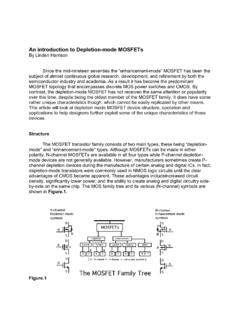
1 2005 Advanced Linear Devices, Inc. Information furnished by Advanced Linear Devices, Inc. (ALD) is believed to be accurate and , ALD assumes no responsibility for the use of such information nor for any infringement of patent or rights of third parties that mayresult from its use. No license is granted implication or otherwise under any patent rights of : MOSFETCIRCUIT IDEAS FOR DESIGNERS Schematic no. Controlled ResistorDescriptionThis CIRCUIT shows an EPAD MOSFET inverter CIRCUIT connected as a Voltage Controlled resistorcircuit.
2 The drain terminal is the output and the gate terminal is the input, which is connected to avoltage reference. The output Voltage VO is determined by the reference input Voltage and theoutput loading R. The drain to source Voltage and the drain current Ids forms one leg of a resistordivider, and the Resistor R forms the other leg of the Resistor divider. Depending on the value of Rselected, the output VO is biased in either negative tempco, zero tempco, or positive tempcomodes. Note that the Resistor R itself also contributes its own tempco term.
3 This CIRCUIT works bestwhen the VO value is kept to a low level, such as at less than If a separate reference voltageis not available, a relatively stable Voltage such as a regulated V+ or a Voltage that is ratio-metricto V+ could be used, at increased VO Components ALD1108xx, ALD1109xx, or any of the EPAD MOSFETsOther Related CIRCUIT IdeasSchematic no. Basic MOSFET/EPAD MOSFET Inverter CircuitSchematic no. Basic MOSFET/EPAD MOSFET Diode-Connected CIRCUIT