Transcription of CL-7 Voltage Regulator Control Installation, …
1 ALARMWARNINGDIAG ERRORCOM 1TX RXCOM 2TX RXCL-7 Regulator ControlESCEDITFUNCSYM1 2 ABC3 DEF4 GHI5 JKL6 MNO7 PQRS8 TUV9 WXYZ0 VOLT LIMITER HIGHOUT-OF-BAND HIGHOUT-OF-BAND LOWVOLT LIMITER LOWAUTO TAP BLOCKEDREVERSE POWERVOLT REDUCTION1 2 3 DATA PORTSUSBDRIVEPCCONTROL FUNCTIONOFFLOCAL MANUALLOWERNEUTRALVOLTMETEREXTERNAL SOURCEINTERNALMOTOR6 ASUPER-VISORYOFFDRAGHANDRESETOFFEXTERNAL POWERAUTO/REMOTE RAISEOFFLOCAL MANUALLOWERNEUTRALVOLTMETERINTERNALMOTOR 6 AOFFVR2 EXTERNALPOWERAUTO/REMOTE RAISEVR3 OFFLOCAL MANUALLOWERNEUTRALVOLTMETERINTERNALMOTOR 6 AOFFEXTERNALPOWERAUTO/REMOTE RAISEENTERCL-7 Voltage Regulator Control installation , Operation, and maintenance InstructionsCOOPER POWERSERIESV oltage Regulators MN225003 ENEffective July 2017 Supersedes June 2016iiINSTALLATION, OPERATION, and maintenance instructions MN225003EN July 2017 DISCLAIMER OF WARRANTIES AND LIMITATION OF LIABILITYThe information, recommendations, descriptions and safety notations in this document are based on Eaton Corporation s ( Eaton ) experience and judgment and may not cover all contingencies.
2 If further information is required, an Eaton sales office should be consulted. Sale of the product shown in this literature is subject to the terms and conditions outlined in appropriate Eaton selling policies or other contractual agreement between Eaton and the ARE NO UNDERSTANDINGS, AGREEMENTS, WARRANTIES, EXPRESSED OR IMPLIED, INCLUDING WARRANTIES OF FITNESS FOR A PARTICULAR PURPOSE OR MERCHANTABILITY, OTHER THAN THOSE SPECIFICALLY SET OUT IN ANY EXISTING CONTRACT BETWEEN THE PARTIES. ANY SUCH CONTRACT STATES THE ENTIRE OBLIGATION OF EATON. THE CONTENTS OF THIS DOCUMENT SHALL NOT BECOME PART OF OR MODIFY ANY CONTRACT BETWEEN THE PARTIES. In no event will Eaton be responsible to the purchaser or user in contract, in tort (including negligence), strict liability or otherwise for any special, indirect, incidental or consequential damage or loss whatsoever, including but not limited to damage or loss of use of equipment, plant or power system, cost of capital, loss of power, additional expenses in the use of existing power facilities, or claims against the purchaser or user by its customers resulting from the use of the information, recommendations, and descriptions contained herein.
3 The information contained in this manual is subject to change without notice. iiiINSTALLATION, OPERATION, and maintenance instructions MN225003EN July 2017 ContentsDISCLAIMER OF WARRANTIES AND LIMITATION OF LIABILITY ..iiSAFETY FOR LIFE ..viSAFETY INFORMATION ..viSafety instructions ..viPRODUCT INFORMATION ..1 Introduction ..1 Read this manual first ..1 Additional information ..1 Acceptance and initial inspection ..1 Handling and storage ..1 Standards ..1 Quality standards..1 Description ..1 SECTION 1: Control FRONT PANEL ..3 Lower panel (grey) ..3 Connecting power to external source terminals ..4 Upper panel (black) ..10 Indicator LEDs ..13 Data ports ..13 Hot-key mapping ..13 SECTION 2: Control installation ..14 Mounting the Control ..14 Placing the Control into service ..14 Operational check ..15 Field calibration check ..16 Removal from service ..17 Removal of Control ..18 Replacement of Control ..18 SECTION 3: INITIAL Control PROGRAMMING.
4 19 Basic programming ..19 Programming and reconfiguring for different Voltage systems ..21 Determination of leading or lagging in delta-connected regulators ..24 SECTION 4: Control OPERATION ..25 Automatic operation ..25 Manual operation ..25 Self-test ..25 Security system ..26 Remote security override ..26 Basic Control operations ..27 SECTION 5: Control PROGRAMMING ..29 Quik-Start setup ..29 Function menu ..31 Function codes ..47ivINSTALLATION, OPERATION, and maintenance instructions MN225003EN July 2017 Special functions ..118 Alarms ..118 Sequence of events (SOE) ..119 Power-up/reset conditions ..120 Indication messages ..120 Metering-PLUS formats ..121 SECTION 6: Control FEATURES ..123 Calendar/clock ..123 Metering ..123 Tap position indication (TPI) ..124 Source-side Voltage ..124 Reverse power operation ..125 Multi-phase Voltage regulation ..134 DeltaCalc feature ..136 Voltage limiter ..137 Voltage reduction ..138 Soft ADD-AMP feature.
5 138 Adaptive ADD-AMP ..138 Supervisory Control and data acquisition (SCADA) ..138 SECTION 7: ADVANCED Control FEATURES ..143 Metering-PLUS feature ..143 USB memory device ..147 Communications ..148 Protocols ..148 Configurable logic ..148 Alarms ..152 Sequence of events (SOE) ..152 Data profiler ..152 TIME-ON-TAP feature ..153 Preventive maintenance tapping ..154 Duty cycle monitor ..154 Leader/follower scheme ..154 Voltage sag monitoring ..154 Fault detection ..156 Heater ..157 Battery options ..157DC power supply ( Vdc) ..157 SECTION 8: TROUBLESHOOTING ..158 External check ..158 Defining the problem ..158 Control panel troubleshooting ..158 Tap-changer operation troubleshooting ..160 Metering troubleshooting ..163 Control calibration ..163 SECTION 9: APPENDIX ..165VR-32 tap connections and Voltage levels ..165 Wiring diagrams and schematics ..167 The instructions in this manual are not intended as a substitute for proper training or adequate experience in the safe operation of the equipment described.
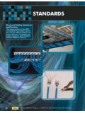
6 Only competent technicians who are familiar with this equipment should install, operate, and service competent technician has these qualifications: Is thoroughly familiar with these instructions . Is trained in industry-accepted high- and low- Voltage safe operating practices and procedures. Is trained and authorized to energize, de-energize, clear, and ground power distribution equipment. Is trained in the care and use of protective equipment such as arc flash clothing, safety glasses, face shield, hard hat, rubber gloves, clampstick, hotstick, is important safety information. For safe installation and operation of this equipment, be sure to read and understand all cautions and instructionsFollowing are general caution and warning statements that apply to this equipment. Additional statements, related to specific tasks and procedures, are located throughout the for life!SAFETYFOR LIFE!SAFETYFOR LIFEE aton meets or exceeds all applicable industry standards relating to product safety in its Cooper Power series products.
7 We actively promote safe practices in the use and maintenance of our products through our service literature, instructional training programs, and the continuous efforts of all Eaton employees involved in product design, manufacture, marketing, and strongly urge that you always follow all locally-approved safety procedures and safety instructions when working around high- Voltage lines and equipment, and support our Safety For Life informationDANGERH azardous Voltage . Contact with hazardous Voltage will cause death or severe personal injury . Follow all locally-approved safety procedures when working around high- and low- Voltage lines and equipment . G103 .3 WARNING Before installing, operating, maintaining, or testing this equipment, carefully read and understand the contents of this manual . Improper operation, handling, or maintenance can result in death, severe personal injury, and equipment damage . G101.
8 0 WARNING This equipment is not intended to protect human life . Follow all locally-approved procedures and safety practices when installing or operating this equipment . Failure to comply can result in death, severe personal injury, and equipment damage . G102 .1 WARNING Power distribution and transmission equipment must be properly selected for the intended application . It must be installed and serviced by competent personnel who have been trained and understand proper safety procedures . These instructions are written for such personnel and are not a substitute for adequate training and experience in safety procedures . Failure to properly select, install, or maintain power distribution and transmission equipment can result in death, severe personal injury, and equipment damage . G122 .3 This manual may contain four types of hazard statements:DANGER Indicates an imminently hazardous situation which, if not avoided, will result in death or serious injury.
9 WARNING Indicates a potentially hazardous situation which, if not avoided, could result in death or serious injury .CAUTION Indicates a potentially hazardous situation which, if not avoided, may result in minor or moderate injury .CAUTION: Indicates a potentially hazardous situation which, if not avoided, may result in equipment damage only .Hazard Statement DefinitionsvINSTALLATION, OPERATION, and maintenance instructions MN225003EN July 2017CL-7 Voltage Regulator Controlhis page is intentionally left , OPERATION, and maintenance instructions MN225003EN July 2017CL-7 Voltage Regulator ControlProduct informationIntroductionThis document describes the operation and maintenance instructions for the CL-7 Voltage Regulator Control for Eaton's Cooper Power series Voltage regulators. Refer to Service Information MN225008EN VR-32 Voltage Regulator with Quik-Drive Tap-Changer installation , Operation, and maintenance instructions for installation and operation information on Eaton's Cooper Power series Voltage this manual firstRead and understand the contents of this manual and follow all locally approved procedures and safety practices before installing or operating this equipment.
10 Read and understand the manual detailing the installation and operation of the Regulator used with this informationThese instructions cannot cover all details or vari ations in the equipment, procedures, or processes described nor provide directions for meeting every possible contin gency during installation , operation, or maintenance . For additional information, please contact your Eaton and initial inspectionThis product is completely assembled, tested, and inspected at the factory. It is carefully calibrated, adjusted, and in good condition when accepted by the carrier for receipt, inspect the carton for signs of damage. Unpack the Control and inspect it thoroughly for damage incurred during shipment. If damage is discovered, file a claim with the carrier and storageBe careful during handling and storage of equipment to minimize the possibility of damage. CAUTION Lifting hazard . A complete Control box assembly with Control can weigh in excess of 50 lbs.