Transcription of Clamp Spacing - Offshore Supplies
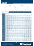
1 Hydraulic & Offshore SuppliesYOUR GATEWAY TO GLOBAL SUPPLYHOSE ASSEMBLIESFLANGESPIPE & TUBEPRESSURE TESTINGEQUIPMENT PACKAGESWALFORMC lamp Spacing Pipeline Products for all IndustriesProduct InformationPipe Clamp Spacing Distance A [mm] [m] 6,0 12,7 1,0 12,7 22,0 1,2 22,0 32,0 1,5 32,0 38,0 2,0 38,0 57,0 2,7 57,0 75,0 3,0 75,0 76,1 3,5 76,1 88,9 3,7 88,9 102,0 4,0 102,0 114,0 4,5 114,0 168,0 5,0 168,0 219,0 6,0 219,0 324,0 6,7 324,0 356,0 7,0 356,0 406,0 7,5 406,0 419,0 8,2 419,0 508,0 8,5 508,0 521,0 9,0 521,0 558,0 10,0 558,0 800,0 12,5 RECOMMENDED DISTANCE BETWEEN CLAMPSBASIC MOUNTING INSTRUCTIONSTHREAD CHARTThe recommended distances between clamps stated below are standard values and are valid for static bends should be supported by STAUFF clamps as near to the bends as , it is recommended to design these clamps as fixed point first Clamp should be placed directly behind the threaded connection or coupling.
2 This protects the threaded connection or coupling from valves are incorporated in the pipelines, it is recommended that support is provided in front of and behind these valvesMetric vs. UNC Thread Metric UNC Group Thread ThreadTWIN SERIES 1D M6 1/4 20 UNC 2D 3D M8 5/16 18 UNC 4D 5D Metric UNC Group Thread ThreadHEAvy SERIES 3S 4S M10 3/8 16 UNC 5S 6S M12 7/16 14 UNC 7S M16 5/8 11 UNC 8S M20 3/4 10 UNC 9S M24 7/8 9 UNC 10S M30 1 1/8 7 UNC 11S M30 1 1/4 7 UNC 12S Metric UNC Group Thread ThreadSTANDARD SERIES 1 1A 2 3 4 M6 1/4 20 UNC 5 6 7 8A HHyyddrraauulliicc&&OOffffsshhoorreeSSuu pppplliieessTel: +44 (0)191 549 7335 Fax: +44 (0)191 516 0004 Email: Website: Products for all IndustriesProduct InformationClamp Loading 1 D M6 5 0,9 5 0,9 2 D 12 2,1 12 2,2 3 D M8 12 1,9 12 2,0 4 D 12 2,7 12 2,9 5 D 8 1,7 8 2,5 3 S 12 1,6 20 4,2 30 12,1 4 S M10 12 2,9 20 4,5 30 15,1 5 S 15 3,3 25 5,1 35 15,5 6 S M12 30 8,2 40 9,3 55 29,4 7 S M16 45 11,0 55 15,8 120 34,9 8 S M20 80 14,0 150 21,0 220 50,0 9 S M24 110 28,0 200 32,0 250 70,6 10 S 180 40,0 350 48,0 500 84,5 11 S M30 200 119,0 370 125,0 500 181,5 12 S 270 168,0 450 180,0 600 244,5 1 8 0,6 10 0,6 12 3,5 1A 8 1,1 10 0,7 12 4,2 2 8 1,3 10 0,8 12 4,3 3 M6 8 1,4 10 1,6 12 4,9 4 8 1,5 10 1,7 12 5,0 5 8 1,9 10 2,0 12 7,3 6 8 2,0 10 2,5 12 8,9 TWIN SERIES (according to DIN 3015, part 3) STANDARD SERIES (according to DIN 3015, part 1)
3 Hexagon Polypropylene Polyamide Aluminum Head Bolt Tightening Max. load in Tightening Max. load in Tightening Max. load in Group DIN EN ISO 4014/4017 torque pipe direction F torque pipe direction F torque pipe direction F (DIN 931/933) [Nm] [kN] [Nm] [kN] [Nm] [kN]All tightening torques and maximum loads in pipe direction refer to clamps with cover plates and hexagon head bolts acc. to DIN EN ISO 4014/4017 (DIN 931/933).The max. load in pipe direction (acc. to DIN 3015, part 10) is an average value,determined by three tests at 23 C with a steel pipe acc. to DIN EN 10220,St37 rolled surface taking static friction into starts when the shown values (F) are SERIES (according to DIN 3015, part 2)F Hexagon Polypropylene Polyamide Aluminum Head Bolt Tightening Max. load in Tightening Max. load in Tightening Max.
4 Load in Group DIN EN ISO 4014/4017 torque pipe direction F torque pipe direction F torque pipe direction F (DIN 931/933) [Nm] [kN] [Nm] [kN] [Nm] [kN] Hexagon Polypropylene Polyamide Head Bolt Tightening Max. load in Tightening Max. load in Group DIN EN ISO 4014/4017 torque pipe direction F torque pipe direction F (DIN 931/933) [Nm] [kN] [Nm] [kN]Tightening Torques And Maximum Loads In Pipe Direction HHyyddrraauulliicc&&OOffffsshhoorreeSSuu pppplliieessTel: +44 (0)191 549 7335 Fax: +44 (0)191 516 0004 Email: Website.