Transcription of ClampOn, Inc. - energydelphos.com
1 clampon , Inc. ultrasonic intelligent Sensors Presented by Hans A. Wagner Locations Bergen, Norway Project Management Engineering and Manufacturing Research and Development Sales and Service for Eastern Hemisphere Houston, Texas Project Management Sales and Service for Western Hemisphere clampon ultrasonic Products DSP Particle Monitor DSP PIG Detector DSP Leak Monitor DSP Corrosion-Erosion Monitor DSP SandQ. DSP Vibration Monitor Versions: Topside Compact Subsea (3048m). Deepwater (4500m). clampon Deepwater Sensors Design depth: 4500m sensor Titanium Funnel 316SS / Carbon Steel clampon Subsea Compact Sensors Design depth: 3048m Retro-fit available All Titanium Construction clampon Subsea sensor Features Jumper interface High pressure chamber with silicon oil Glass-metal penetrator Atmosphere chamber Electronic beam welding No gaskets or mechanical sealing clampon DSP-06 Particle Monitor Topside Ex ia Top-entry / side-entry Intrinsically safe IP68.
2 Weight: 2,6 / 3kg All parts are SS316. clampon DSP-06 Particle Monitor Topside Ex de Explosion proof IP68. Weight: 7kg All parts are SS316. Particle Monitor Working Principal clampon Acoustic Sand Monitors measures the ultrasonic frequency (energy) generated by solids impacting the side-wall of a pipe, normally after a bend. Predicted Penetration Rate (Standard Elbow - 10,000 Particles Simulated). Maximum Erosion Flow mpy Flow 0. Frequency Spectrum Proper filtering will remove most of the signal not related to particles, while still keeping an extremely high sensitivity to particles. Spectrum - Response from different media 100. 90. Sand /. 80. Particle 70. Level %. 60. 50. 40. Gas /. 30. Liquid Mechanical 20 Water / Liquid 10. 0. Frequency Measurement Options Qualitative Measurement No need for other input Standalone system Sand Alarm First sand production, screen failure etc.
3 Sand production trending Finding Maximum Sand Free Rate (MSFR). Quantitative Measurement Requires input of flow data / flow speed How much sand are you producing Finding Maximum Acceptable Sand Rate (MASR). Quantifying the Signal The particles are quantified by applying the measured ultrasound signal and flow information to an algorithm. Quantifying the Signal Kinetic Energy = Mass * Velocity2. (Raw Value-Zero) = Sand Rate * Step Sand Rate = (Raw Value-Zero) / Step Raw Value = sensor Output (Acoustic Energy). Zero = Sand Free Raw Value Step = Calibration Factor related to velocity Alarming Average sand rate Average sand rate 58 Average sand rate 45. 3 slugs, 1 lb each lbs/day Amplitude lbs/day Amplitude = lbs/day Amplitude =. Amplitude = 5000 = 2136 2629 2154 5237 2295 2765. 8000 Total 1 lbs for period Total 5 lbs for period Total 11 lbs for period 3 hour period 4 hour period 2 hour period 6 hour period Amplitude: Amplitude alarms are often used, but may miss significant quantities, produced over a period of time.
4 Sand rate: Sand rate alarms may be based on erosion models, but should include delays to minimize nuisance alarms. Mass: Mass alarms focus on the quantity of sand produced rater than the real time sand measurement. Benefits of Training / Service Subsea & Topside Field Calibration Trend 100 Grams Majority 180-250 Micron 50,25,10 Grams 100 Grams Majority 80-100 Micron Average 20 Micron Well Testing Trend Startup Ramp Up Ramp Up Slugging Trend clampon DSPII. Next generation technology, available today. DSPII capabilities include: Increased processing power Increased memory capacity Simultaneous measurements, sand, flow, vibration Capable of running complex algorithms internally DSPII Internal Processing DSPII processing allows the sand calculation to be performed internally by the sensor . Configuration and calibration and real time calculated data is available over the Modbus protocol.
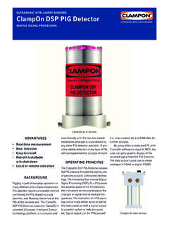
5 SandQ Benefits The SandQ Monitor will provide flow information/data directly from the FlowQ . The SandQ Monitor will recognize/detect well flowing changes The SandQ Monitor will detect particles simultaneously with the FlowQ . The SandQ system can be implemented in the existing clampon DSP-06 already installed system with a small Plug-In module in the software to give it upgraded capabilities (DSPII). SandQ Features Flow sensing element, FlowQ . Sand sensing element Vibration element 3-axis Real time clock Digital Signal Processor SandQ Increased Accuracy Calibration adjusted in real time in response to upset Real time flow measurement at the sensor location provides greater accuracy by allowing real time calibration adjustment for flow fluctuations clampon DSP PIG Detector Intrinsically Ex ia Available Outputs: 2x Relay, 4-20 mA, RS 485.
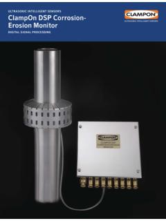
6 Field configuration updates via computer Power from safe area: 12- 24 VDC 110-220 VAC. clampon DSP PIG Detector - Ex dem w/Local Indication (Lamp) and Reset Function General: Explosion proof (Ex d). No need for safe area equipment Ex e terminal box with light and reset 2 x Relay, 4-20mA, RS485 - Outputs 24 VDC power input 2 x M20 entries clampon Corrosion-Erosion Monitor Cost effective solution for assessing wall thickness loss in pipelines - quantitatively - using Guided Wave technology to optimize output Working Principal AGLW = Acoustic Guided Lamb Waves Named after Horace Lamb, who discovered the waves in 1916. The pipe wall will force the transmitted signal into a given shape and form (mode generation). Analytical inversion of acoustic data to obtain relevant thickness information Dry Contact Transducers - CEMAT - Transducers can be mounted on the outside of coating <1mm thickness Measures WT between the transducers in line of sight.
7 Resolution/sensitivity better then 1% of WT. Signal is Robust and will not break down Dry Contact Transducers - CEMAT - Transducers can be mounted on the outside of coating <1mm thickness Measures WT between the transducers in line of sight . Resolution/sensitivity better then 1% of WT. Signal is Robust and will not break down CEM Coverage Area The figure illustrates the area covered by a pair of transducers Beam divergence allows the CEM to see a large area A matrix of transducers deployed on a region of pipe can provide comprehensive coverage Transducer 1 Transducer 2. The larger the WT, the larger the coverage area CEM - Coverage Area OD pipe 8 . Separation 700 mm 6 Transducers set-up Total Coverage: 90% (of inspected area). Each path width is 70mm Pipe Unfolded Bottom Pipe / Plate CEM - Coverage Area 5 4.
8 7 1 Top line 8 3. Transducers Bottom OD pipe 8 Total Coverage: Separation 700 mm 90% - topline corrosion 6 Transducers set-up Software generated CEM Subsea Corrosion-Erosion Monitor - 3 Alternative models available - - CEM for ROV installation - CEM under insulation/coating - CEM w/mechanical cover CEM Transducers Under Insulation/Coating CEM Subsea System Main Parts Transducers Electronic w/CEM Controller Power 4 Transducers Power 4 Transducers Electronic up to 7 meters from transducers UP TO 32 Transducers can be CONNECTED to the Canister Verification of Stability CEM system tested with heating & cooling Standard deviation: Temp. range 10 - 170C. Example Detection Pitting Corrosion . Pitting corrosion was simulated by drilling small holes in a 1x1m and approximately 22mm ( ) thick steel plate.
9 The clampon CEM shows a average loss of about 1%. UT measurements conducted in a thorough manner at 14 points along the measurement path showed no corrosion. Pitting Corrosion % change CEM measurements UT Readings 9:02 9:31 10:00 10:29 10:58 11:26 11:55 12:24 12:53. CEM Test 6" Bend ConocoPhillips Technology Center, Bartlesville, OK. Area Subsea CEM Technical Data Pipe outer diameter (OD): min 4 (100 mm). Pipe wall thickness (WT): 2 mm to 35 mm (0,08 to 1,38 ). Distance between transducers: m 2 m (78 ) typical Temperature : -40 to 180 C (-40 to 356 F ). Frequency range: 30 to 300 kHz Sensitivity: (smallest change better than 1% of the pipe wall that can be reliably detected) thickness typical Repeatability: Power consumption: Avg 6 Watt - Max 10 Watt Sleep Mode: 0,001mA. Battery Pack: 5 years with data point weekly sensor electronics: DSP 66-MIPS, A/D con.
10 24bit, 25-Years Installation: Vertical & Horizontal Water depth: 3000 Meters Test pressure: 345 BarA. Operational Data Operating mode: Active acoustic - Guided Lamb waves Number of transducers: Minimum 2, current 8 by Q4 32. Transducer type: Electromagnetic Acoustic Transducers CEMATs can be mounted without any acoustic couplant. Makes the system relocatable not necessarily a permanent installation. Provides better thermal stability than standard piezoelectric transducers. Maximum cable length 3000 m, 4 core cable ( ). Various wireless and battery powered solutions available. Output data: ModBus, TCP/IP, RS485. Maximum number of sensors/electronic units per communication line: 12. Maximum temperature for insulation: 130oC (266oF) -Hyperlast etc. Pipe material All metal pipes Calibration Once, on installation Operation life: 220 000 hours clampon Service System quality checks and upgrades Alarm recommendations Adjustment of software parameters Field calibration with a sand injector Standardized analysis and reporting Assist with developing monitoring procedures for control room Training of company personnel as required Sand Management services