Transcription of CLUTCH INSTALLATION INSTRUCTIONS & …
1 CLUTCH INSTRUCTIONS B082906 1. These INSTRUCTIONS apply to all PowerTrain Technology, Inc. (PTT) multi-disc racing clutches from 4- up to 7- disc diameter. Before proceeding, ensure that you have selected, and received the correct CLUTCH for your application. 2. Any components that may affect CLUTCH performance must be in good condition and suitable for the use for which they are intended. IE: Bellhousing, flywheel, CLUTCH release system, pilot bearing, etc. 3. Check the pilot bushing in the crankshaft. It should have a hole of proper size, with no evidence of metal chips, out of roundness, cracking or splitting. A PTT Spline-A-Lign CLUTCH alignment shaft can be used for checking the proper size of the pilot bushing. It has a properly sized pilot on the end. Simply insert it into your pilot bushing and check for excess play.
2 4. The transmission input shaft must be accurately aligned to the engine crankshaft. The bellhousing performs this critical alignment function. Check your bellhousing to insure that the transmission register hole is concentric within ( ) total indicated run-out, to the engine crankshaft. The back of the engine block has to be parallel to the transmission mounting surface of the bellhousing within ( ) or less. Detailed INSTRUCTIONS for this inspection procedure can be found at the PTT website ( ). Performing this step avoids excessive spline wear on the CLUTCH hubs and input shaft. It also helps prevent cracked CLUTCH discs, hard shifting, and other problems. 5. Ensure the input shaft and CLUTCH disc splines are clean and dry. Do not lubricate. Check the new CLUTCH disc(s) splines for proper engagement on your input shaft.
3 They must fit easily on the input shaft spline and not bind, overhang or bottom out. Take the opportunity now to look at the input shaft spline closely to insure that it is not worn, pitted, corroded, or twisted. 6. Install the CLUTCH bolts that came with your CLUTCH , from the backside of the flywheel. (Some flywheels do not require this.) Check the crank flywheel mounting surface for corrosion, pitting, scratches, or imbedded debris. The flywheel must be able to sit absolutely flat on the crank mounting surface, with no evidence of rocking. Install the flywheel. Torque the flywheel mounting bolts according to the engine or crank manufacturer s INSTRUCTIONS . PTT recommends the use of a medium strength anaerobic thread locking compound. (Loctite , or similar product) DO NOT USE STAR WASHERS! 7. Check to see that the CLUTCH disc nearest the flywheel is not in interference with the flywheel bolts or crankshaft.
4 8. Degrease the metallic CLUTCH discs, floater plate(s), pressure plate and the flywheel prior to INSTALLATION . Keep organic facings clean and dry, taking special care to avoid oil or grease contamination. 9. Ensure that the CLUTCH is assembled correctly. If your discs are labeled showing CLUTCH disc orientation, install the CLUTCH discs according to the labels. On one disc clutches the rivet head stamped PTT faces towards the engine. On two disc clutches, the flat rivet heads, stamped PTT, must be facing each other. On three disc clutches, the flat rivet heads stamped PTT on the two end hubs must face each other, & the center disc can be installed in either direction. Four disc clutches need to have the rivet heads aligned all in the same direction. Please refer to the drawing below for proper hub assembly or to the INSTRUCTIONS that came with your CLUTCH .
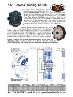
5 NOTE: All CLUTCH packs shown here are transmission side up, engine/flywheel side down. CLUTCH INSTALLATION INSTRUCTIONS & TECHNICAL GUIDE 355 Point Court Ph: Algonquin, IL 60102 Fax: CLUTCH INSTRUCTIONS B082906 10. Center up and align the CLUTCH disc splines. Locate the CLUTCH over the flywheel register. PTT clutches are designed to locate on a flywheel register that is ( ) tall. Flywheel CLUTCH register diameters are as follows: 4 Clutches: / ( / ) 5 Clutches: / ( / ) 7 Clutches: / ( / ) 11. Insert a CLUTCH disc alignment tool into the CLUTCH . A PTT Spline-A-Lign is a premium quality, affordable, all metal tool that is perfect for the job. Install the washers, and self locking nuts that came with your CLUTCH . Tighten the CLUTCH retaining bolts evenly, checking to see that the CLUTCH cover has seated correctly.
6 Final CLUTCH retaining bolt torque is as follows: 4 clutches 10-12 5 clutches 18 max. 7 clutches 18 max. 12. The CLUTCH release bearing must incorporate a radiused contact face, not a flat face. See your authorized PTT dealer for the proper PTT release bearing for your CLUTCH . Minimum contact diameter = (42mm) - recommended size, most clutches Standard contact diameter = ( ) - suitable for most clutches Maximum contact diameter = (51mm) - only suitable for use with 7 clutches 13. The CLUTCH release bearing contact position will gradually move toward the transmission throughout the normal life of the CLUTCH . To allow for this the CLUTCH release bearing system MUST be able to accommodate an initial clearance of at least ( ) between CLUTCH bearing and point of contact on the CLUTCH diaphragm spring PLUS at least the maximum allowable travel to release the CLUTCH .
7 CLUTCH release travel, as measured at the release bearing, is as follows: 4 clutches ( ) 5 clutches ( ) 7 clutches ( ) 14. The CLUTCH release bearing system MUST be set-up with operating clearance between the CLUTCH release bearing and the diaphragm spring fingers. It may be necessary to disable any CLUTCH cable auto adjust system and convert to full manual adjustment. 15. The CLUTCH pedal MUST be fitted with a positive pedal stop. It should be adjusted to allow sufficient travel to prevent CLUTCH drag, and yet not exceed the maximum allowable stroke for the CLUTCH installed. Ensure the CLUTCH actuation system is set to operate within its normal range. Failure to closely follow steps 12 thru 15 could result in serious damage to, or premature failure of your PTT CLUTCH . 16. Inspect your CLUTCH at frequent intervals.
8 This interval will vary depending on use. Replace the CLUTCH disc(s) when they are worn to the minimum thickness. This avoids CLUTCH slippage which leads to excess heat that can permanently damage your CLUTCH . CLUTCH disc wear limits are as follows: Number Thickness, Thickness, Thickness, Thickness, of Discs: New: Worn: New: Worn: 1 ( ) ( ) ( ) ( ) 2 ( ) ( ) ( ) ( ) 3 ( ) ( ) ( ) ( ) 4 ( ) ( ) At the end of the racing season your CLUTCH should have a thorough service & inspection. Your dealer may be able to offer this service, or you can have this service performed at the PTT factory.
9 See our website for details. With proper care & maintenance your PTT CLUTCH will last many seasons of racing. IF IN DOUBT, CHECK WITH YOUR DEALER OR POWERTRAIN TECHNOLOGY FOR FURTHER ADVICE!