Transcription of CO CAPTURE TECHNOLOGIES - Global CCS Institute
1 CO2 CAPTURE TECHNOLOGIES . POST COMBUSTION CAPTURE (PCC). JANUARY 2012. Global CCS Institute CO2 CAPTURE TECHNOLOGIES . CONTENTS. POST COMBUSTION CAPTURE (PCC) .. 3. Basic Descriptions of Post-Combustion 3. Influence of fuel .. 3. Near-Term TECHNOLOGIES .. 4. Fluor Econamine FG PlusSM and Other MEA Processes .. 5. MHI KM-CDR Process .. 5. Alstom Chilled Ammonia Process (ACAP) .. 6. Powerspan ECO2 Process .. 6. Cansolv .. 6. Aker Clean Carbon .. 7. Alstom Advanced Amine Process .. 7. Siemens POSTCAP Amino Acid Salt .. 7. HTC Purenergy / Doosan Babcock .. 7. Other Solvent Processes .. 8. Major Challenges and R&D Trends .. 8. CAPTURE Methods .. 8. Absorption .. 9. Adsorption .. 9. Membranes.
2 10. Current Status .. 11. The Future of Post-Combustion CAPTURE Technology .. 13. ACRONYMS AND SYMBOLS .. 15. CO2 CAPTURE TECHNOLOGIES , Section 2 1. Global CCS Institute CO2 CAPTURE TECHNOLOGIES . DISCLAIMER OF WARRANTIES AND LIMITATION OF LIABILITIES. THIS DOCUMENT WAS PREPARED BY THE ORGANIZATION(S) NAMED BELOW AS AN ACCOUNT OF WORK SPONSORED OR. COSPONSORED BY THE ELECTRIC POWER RESEARCH Institute , INC. (EPRI). NEITHER EPRI, ANY MEMBER OF EPRI, ANY. COSPONSOR, THE ORGANIZATION(S) BELOW, NOR ANY PERSON ACTING ON BEHALF OF ANY OF THEM: (A) MAKES ANY WARRANTY OR REPRESENTATION WHATSOEVER, EXPRESS OR IMPLIED, (I) WITH RESPECT TO THE USE OF. ANY INFORMATION, APPARATUS, METHOD, PROCESS, OR SIMILAR ITEM DISCLOSED IN THIS DOCUMENT, INCLUDING.
3 MERCHANTABILITY AND FITNESS FOR A PARTICULAR PURPOSE, OR (II) THAT SUCH USE DOES NOT INFRINGE ON OR. INTERFERE WITH PRIVATELY OWNED RIGHTS, INCLUDING ANY PARTY'S INTELLECTUAL PROPERTY, OR (III) THAT THIS. DOCUMENT IS SUITABLE TO ANY PARTICULAR USER'S CIRCUMSTANCE; OR. (B) ASSUMES RESPONSIBILITY FOR ANY DAMAGES OR OTHER LIABILITY WHATSOEVER (INCLUDING ANY CONSEQUENTIAL. DAMAGES, EVEN IF EPRI OR ANY EPRI REPRESENTATIVE HAS BEEN ADVISED OF THE POSSIBILITY OF SUCH DAMAGES). RESULTING FROM YOUR SELECTION OR USE OF THIS DOCUMENT OR ANY INFORMATION, APPARATUS, METHOD, PROCESS, OR SIMILAR ITEM DISCLOSED IN THIS DOCUMENT. REFERENCE HEREIN TO ANY SPECIFIC COMMERCIAL PRODUCT, PROCESS, OR SERVICE BY ITS TRADE NAME, TRADEMARK, MANUFACTURER, OR OTHERWISE, DOES NOT NECESSARILY CONSTITUTE OR IMPLY ITS ENDORSEMENT, RECOMMENDATION, OR FAVORING BY EPRI.
4 THE FOLLOWING ORGANIZATION(S), UNDER CONTRACT TO EPRI, PREPARED THIS REPORT: EPRI. This document has been derived from material in the report sponsored by the Global Carbon CAPTURE and Storage Institute , Canberra, Australia. CO2 CAPTURE TECHNOLOGIES July 2011. CO2 CAPTURE TECHNOLOGIES , Section 2 2. Global CCS Institute CO2 CAPTURE TECHNOLOGIES . POST COMBUSTION CAPTURE (PCC). Basic Descriptions of Post-Combustion CAPTURE Post-combustion CAPTURE (PCC) refers to the separation of CO2 from flue gas derived from combusting fossil fuels coal, natural gas, or oil in air. In the case of coal-based power, as shown in Figure 1-1, coal is combusted in air and the liberated heat is converted to electricity by steam-driven turbines connected to generators.
5 The combustion results in a flue gas mixture consisting of N2, CO2, H2O, O2, and a host of compounds such as SOx, NOx, and heavy metals amongst others. Some of these are removed using existing TECHNOLOGIES such as selective catalytic reduction (SCR), electrostatic precipitation (ESP), and flue-gas desulphurization (FGD). A PCC process then aims to selectively separate CO2 from the remaining gas mixture as shown in Figure 2-1. After CAPTURE , CO2 can be compressed and stored underground, used in some other processes such as enhanced oil recovery (EOR), or used in some other capacity that does not result in its emission into the atmosphere. Fresh Water Reduce Reduce Reduce NOx Ash CAPTURE CO2.
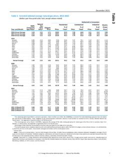
6 Sulphur Coal PC CO2. Removal Flue Gas Boiler SCR ESP FGD. Air , MEA to Stack Steam Gypsum/Waste CO2 for compression Turbine Fly Ash and storage, EOR, or other use Figure 2-1. A Typical Post-Combustion Carbon CAPTURE Process. Influence of fuel Table 2-1 shows the representative concentration of post-combustion flue gas for coal- and gas-fired power plants. There is additional variation around these values depending on the exact composition of the fuel , the efficiency of the plant, types of emission controls installed, and other factors, but for purposes of CO2 CAPTURE , 10-15% CO2 for coal and 4-5% for natural gas are quite representative. CO2 CAPTURE TECHNOLOGIES , Section 2 3. Global CCS Institute CO2 CAPTURE TECHNOLOGIES .
7 Table 2-1 Typical Compositions of Flue gases from Coal- and Gas-fired Power Plants. Gas Constituent Coal Natural Gas (Gas Turbine). Nitrogen (N2) 70-75% 73-76%. Carbon Dioxide (CO2) 10-15% 4-5%. Water Vapour (H2O) 8-15% 8-10%. Oxygen (O2) 3-4% 12-15%. Trace Gases (SOx, NOx, others) <1% <1%. Carbon is the predominant combustion species in coal, while both carbon and hydrogen are combusted in natural gas; thus, for each CO2 molecule generated during combustion, coal has less energy release. This results in coal power plants typically generating twice as much CO2 as gas power plants for the same power output, about 1 g CO2/kWh vs. g CO2/kWh. However, flue gas from coal power plants has more concentrated CO2 relative to natural gas.
8 This results in CO2 CAPTURE consuming less energy for coal power plants relative to gas power plants for the same mass of CO2 captured. The net result in terms of parasitic load on the host power plant and cost of electricity increase due to the CAPTURE process therefore is not straight forward particularly with the range of coal and natural gas prices. Due to the predominance of coal in power production and the likelihood of CO2-control regulations impacting those most, the overwhelming emphasis of CAPTURE process developers has been on coal-fired power plants. Research and development for CAPTURE on natural gas fired power plants is relatively scarce, though regulations may require natural gas fired power plants to have CO2 emission controls similar to that expected for coal fired power plants.
9 Near-Term TECHNOLOGIES PCC TECHNOLOGIES that can be considered near-term have been tested at scales on slip streams no larger than 5-25 MWe from coal-fired power plants. Press releases and other announcements have been made for projects intended for larger sizes, but these are planned future projects. All near-term TECHNOLOGIES are solvent- based involving either ammonia or proprietary amines. The distinction between these TECHNOLOGIES is specific CAPTURE chemistry and, to some extent, the process configuration and integration into the power plant. The specific CAPTURE chemistry can be contaminated by the presence of other acid-forming gases such as SO2 and SO3, and therefore all of these near-term TECHNOLOGIES require SOx concentrations typically no higher than 10.
10 Ppmv in order to minimize solvent usage and cost TECHNOLOGIES that could be called near-term include Fluor's Econamine FG+, Mitsubishi Heavy Industries KS. solvent, Cansolv TECHNOLOGIES , Aker Clean Carbon, and Alstom's Chilled Ammonia Process (ACAP). All of these use either aqueous pure amines or blends of amines, with the exception of Alstom's CAP which uses aqueous ammonium carbonate to bicarbonate reaction. In all these near-term TECHNOLOGIES , an absorber- stripper configuration is used as shown in Figure 2-1, with the solvent regenerated thermally using steam from the power plant. This steam extraction results in loss of power production at the host plant, and when combined with power needed for compression, results in a parasitic load of 20-30% for CO2 CAPTURE and compression, with net plant efficiency dropping from 38% to 27%.