Transcription of COIL PITCH IN AN AC ARMATURE WINDING FULL …
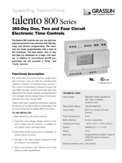
1 COIL PITCH IN AN AC ARMATURE WINDING full PITCH WINDING The distance between the two sides of an individual coil of an AC ARMATURE WINDING is termed the coil PITCH . When the angular distance between the sides of a coil is exactly equal to the angular distance between the centers of adjacent field poles, the coil is termed to be a full PITCH coil. An ARMATURE WINDING made up of full PITCH coils is termed a full PITCH WINDING . In the figure below, angle A (the angular distance between coil sides) is 90 mechanical degrees, and the angular distance between adjacent pole centers is 90 mechanical degrees. Therefore, the coil PITCH is 90 over 90 , or a 1 PITCH . In addition, the angular distance between coil sides and adjacent pole centers is also measured in electrical degrees. The angular distance between adjacent pole centers is 180 electrical degrees, and so the angular distance between the coil sides of a full PITCH coil is also 180 electrical degrees.
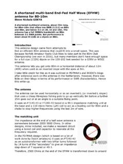
2 COIL PITCH IN AN AC ARMATURE WINDING FRACTIONAL PITCH WINDING When the angular distance between the sides of a coil is less than the angular distance between the centers of adjacent field poles, the coil is termed to be a fractional PITCH coil. An ARMATURE WINDING made up of fractional PITCH coils is termed a Fractional PITCH WINDING . In the figure below, angle A (the angular distance between coil sides) is 60 mechanical degrees, or 120 electrical degrees, and the angular distance between adjacent pole centers is 90 mechanical degrees, or 180 electrical degrees. Therefore, the coil PITCH is 60 over 90 (120 over 180 ), or a 2/3 PITCH . COIL PITCH IN AN AC ARMATURE WINDING CALCULATING PITCH FACTOR TERMS 1. Coil Throw: The location in an ARMATURE core of the sides of a coil starting in slot number one (1). Example: the throw could be 1 to 9 meaning that one side of the coil is inserted in slot #1, and the other side in slot #9.
3 2. Coil Span: The number of core slots spanned by the sides of the coil. In the above example, the span would be 8 slots (9 1). 3. Slots Per Pole: The number of slots in the ARMATURE core divided by the number of poles constituting the field. Example: In a 4 pole generator having a 48 slot ARMATURE core, the number of slots per pole would be 48 4, or 12 slots per pole. PITCH FACTOR CALCULATION PITCH Factor is calculated by dividing the coil throw ( ) 1 (coil span), by the number of slots per pole. Using the examples in 1 through 3 above: 1 to 9 throw (-) 1 8 PITCH Factor = = 48 Slots 4 Poles 12 PITCH Factor = 2/3 COIL PITCH IN AN AC ARMATURE WINDING AS A DESIGN TOOL FOR MINIMIZING HARMONIC CONTENT IN THE GENERATED VOLTAGE SINE WAVE One of the design considerations in selecting an appropriate PITCH factor is the harmonic content of the generated voltage wave form.
4 PITCH factor can be used to reduce or eliminate specific harmonic frequencies in the generated voltage wave form as follows: A. full PITCH : A full PITCH will have no damping effect on any harmonic frequency. B. 2/3 PITCH : A 2/3 PITCH will eliminate the third harmonic and subsequent triplens : 9th, 15th, 21st, 27th, .. etc. C. 4/5 PITCH : A 4/5 PITCH will eliminate the 5th harmonic. D. 6/7 PITCH : A 6/7 PITCH will eliminate the 7th harmonic. E. 5/6 PITCH : A 5/6 PITCH will: 1. Minimize the 5th harmonic, but not eliminate it as will a 4/5 PITCH . 2. Minimize the 7th harmonic, but not eliminate it as will a 6/7 PITCH .