Transcription of Combined Heat and Power Technology Fact Sheet Series - …
1 Combined Heat and Power Technology Fact Sheet SeriesADVANCED MANUFACTURING OFFICEA bsorption Chillers for CHP SystemsChillers are used in commercial buildings and industrial plants to provide air conditioning, refrigeration, and process fluid cooling . There are two basic types of chiller cycles: vapor compression and sorption. Vapor compression chillers use reciprocating, screw, or centrifugal compressors to Power the cycle. The compressors are most often driven by electric motors, although they can also be powered by natural gas engines or steam turbines. Sorption chillers, which are avail-able as either absorption or adsorption designs1, are driven with thermal energy produced from a direct fired burner integrated with the chiller, or with thermal energy supplied indirectly to the chiller. Indirect thermal sources include hot water , steam, or combustion exhaust. Absorption chillers are often exhaust fired using thermal energy recovered from Combined heat and Power (CHP) prime movers ( , recip-rocating engines, microturbines, and combustion turbines).
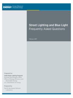
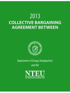
2 Table 1 provides an overview of absorption chiller use in CHP chillers use a binary solution of a refrigerant and an absorbent, and different solutions allow absorption chillers to meet a range of site cooling needs. For space conditioning and other requirements that require chilling fluid temperatures of 40 F or higher, water /lithium bromide (refrigerant/absorbent) is the most common solu-tion. For lower temperatures, am-monia/ water (refrigerant/absorbent) is typically used. Absorption chillers are most cost effective at sites that have significant space conditioning requirements or year-round cooling loads. Applications with significant year-round space conditioning loads include hospitals, hotels, large com-mercial office buildings, and college campuses. Sites that may require steady year-round cooling include manufacturing plants with process cooling needs, cold storage warehouses, data centers, and district energy 400-ton single-stage absorption chiller integrated with three 600 kW reciprocating engines provides hot water for process and space heating.
3 The system is located at a metal fabrication facility in Fitchburg, Massachusetts. Photo courtesy of Northeast CHP Technical Assistance Partnership (CHP TAP).Table 1. Summary of Absorption Chiller Attributes for CHP SystemsSize range5 to 3,000 refrigeration tonsInput HeatHot water , steam, or prime mover exhaust ConfigurationAvailable in single and two stage designs. Single stage machines can be driven with hot water (200-240 F) or low pressure steam (15 psig) and are often used with reciprocating engine CHP installations. Compared to single stage chillers, two stage machines require higher temperature hot water ( , 350 F) or higher pressure steam ( , 115 psig) and are often used with combustion turbine CHP installations. In addition to hot water and steam, absorption chillers can also be exhaust fired (required exhaust temperatures typically above 750 F).Refrigerant / Absorbent For 40 F and higher chilling fluid temperatures ( , building air conditioning), a common mixture is water (refrigerant) and lithium bromide (absorbent).
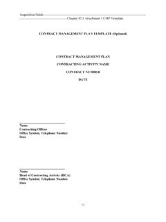
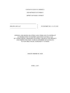
4 For chilling fluid temperatures below 40 F ( , cold storage), a common mixture is ammonia (refrigerant) and water (absorbent).1 Absorption chillers use fluid refrigerants and absorbents. Adsorption chillers use a solid sorbent (typically silica gel) and a fluid refrigerant (typically water ).Figure 1. Single stage absorption cycle. Graphic credit Exergy PartnersTechnology DescriptionThe absorption cycle is similar to the vapor compression cycle except the prime mover (typically an electric motor) and com-pressor are replaced by a thermal compressor system consisting of an absorber, solution pump, and generator (see Figure 1). Like a mechanical compressor in a vapor compression chiller, the thermal compressor takes low pressure/low temperature refrigerant vapor from the evaporator and delivers high pressure/high temperature refrigerant vapor to the refrigerant condenser.
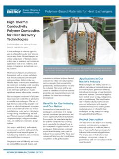
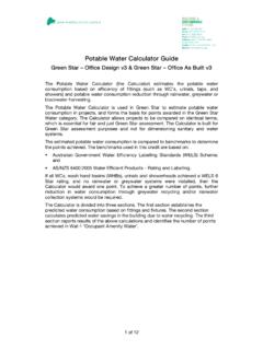
5 Instead of directly compressing the refrigerant vapor using a large amount of mechanical energy (typically electricity), a ther-mal compressor uses an absorbent fluid to chemically bond with Ammonia/ water absorption chiller integrated with a CHP system consisting of two reciprocating engines. Photo courtesy of Energy refrigerant vapor (essentially compressing it by changing phase from a gas to a liquid). This dilute solution of absorbent/refrigerant is easily pumped to the generator using a relatively small electric pump. In the generator, the refrigerant is boiled us-ing thermal energy, and the refrigerant vapor then migrates to the condenser where it is changed back into a liquid refrigerant to begin the process over again. The absorbent is returned from the generator to the absorber to bond again with refrigerant vapor. The absorption process is exothermic ( , it generates heat), and heat must be rejected from the absorber to the condenser water and cooling tower loop.
6 Because of this additional heat rejection load, absorption chillers require a larger cooling tower compared to a mechanical chiller with the same basic absorption cycle shown in Figure 1 is the same for both water /lithium bromide and ammonia/ water absorption chillers. The difference is that ammonia/ water chillers can serve lower temperature cooling requirements ( , refrigerated warehouses for cold storage) compared to water /lithium bromide systems. The picture on the left shows a CHP system with an integrated ammonia/ water absorption chiller. This installation consists of two 415 kW reciprocating engine generators and an absorption chiller that produces 160 tons of 25 F refrigeration from the engine waste heat. The 160 tons of refrigeration is supplied directly to a cold room at a food processing plant where 1,900 gallons per minute of refrigerant (ammonia) cascades over the evaporator coils.
7 ADVANCED MANUFACTURING OFFICE2 Performance CharacteristicsThe efficiency of an absorption chiller is measured by the coef-ficient of performance (COP), which is defined as useful thermal energy output ( , chiller load) divided by heat input. COP is a unit-less number and does not include energy consumed by pumps, fans, or other ancillary components. COP values for single stage chillers are less than one, and COP values for two stage systems are greater than one ( , chilled energy delivered exceeds heat required to drive the system). Because absorption chiller capacity is a function of thermal energy input quantity and quality, as well as chiller design (single or two stage), it is important to match CHP prime movers with the right absorption chiller. While a two stage absorption chiller has a higher COP compared to a single stage chiller, a two stage chiller also requires a generator temperature about 150 F higher than a single stage chiller.
8 Where high temperature heat sources are available, either design can be used. While a two stage heat recovery absorption chiller can produce more capacity from a high temperature heat source compared to a single stage chiller, a single stage chiller is less complex and typically less 2 shows representative performance characteristics for single and two stage water /lithium bromide absorption chillers ranging in capacity from 50 to 1,320 tons. Three capacities are included for single stage chillers (Systems 1-3), and four capacities are included for two stage units (Systems 4-7). The three single stage examples are based on using either hot water or low pressure steam to drive the absorption chiller. The four two stage examples are based on using either high pressure steam or CHP prime mover exhaust as the heat source. All seven systems deliver 44 F chilled water based on an inlet water temperature of 54 F.
9 The three single stage absorption chillers have COP values of to , and the four two stage units, which are more efficient compared to single stage designs, have COP values of to Characteristics for the thermal ADVANCED MANUFACTURING OFFICE3 Table 2. Absorption Chiller Performance Characteristics (typical values for water /lithium bromide chillers)DescriptionSystem1234567 DesignSingle stageTwo stageHeat SourceHot WaterSteam (low pressure)Steam (high pressure)Exhaust Fired Nominal cooling Capacity (tons)504401,3203301,3203301,000 Thermal Energy InputHot water Inlet Temp ( F)190208n/an/an/an/an/aHot water Outlet Temp ( F)181190n/an/an/an/an/aSteam Pressure (psig)n/ Gas Temperature ( F)n/an/an/an/an/a530850 Heat Required (MMBtu/hr)2 Output (chilled water )Inlet Temperature ( F)54 Outlet Temperature ( F)44 cooling COP (full load) : Performance characteristics are based on multiple sources, including vendor data and discussions with industry experts.
10 The characteristics are intended to illustrate typical absorption chillers, and are not intended to represent performance of specific F or the hot water and steam examples, the boiler efficiency is not considered in the 3. Absorption Chiller Capital and O&M Costs (typical values for water /lithium bromide chillers)DescriptionSystem1234567 DesignSingle stageTwo stageHeat SourceHot WaterSteam (low pressure)Steam (high pressure)Exhaust Fired Nominal cooling Capacity (tons)504401,3203301,3203301,000 Equipment Cost ($/ton)$2,010$930$820$1,190$1,000$1,330$ 930 Construction and Installation ($/ton)$3,990$1,370$980$1,810$1,200$1,97 0$1,070 Installed Cost ($/ton)$6,000$2,300$1,800$3,000$2,200$3, 300$2,000O&M Costs ( / ton-hr) : Costs are based on multiple sources, including vendor data and discussions with industry experts. The values shown are compos-ite results, and are not intended to represent a specific MANUFACTURING OFFICE4energy that drives the seven absorption chillers shown in the table are: hot water temperature of 190 to 208 F (Systems 1 and 2, respectively), steam pressure of psig (System 3, low pressure), steam pressure of 116 psig (Systems 4 and 5, high pressure), and exhaust gas temperature of 530 to 850 F (Systems 6 and 7, respectively).