Transcription of Combined Heat and Power Technology Fact Sheets Series ...
1 Combined Heat and Power Technology Fact Sheet SeriesReciprocating EnginesReciprocating internal combustion engines are a mature tech-nology used for Power generation, transportation, and many other purposes. Worldwide production of reciprocating internal combustion engines exceeds 200 million units per For CHP installations, reciprocating engines have capacities that range from 10 kW to 10 MW. Multiple engines can be inte-grated to deliver capacities exceeding 10 MW in a single plant. Several manufacturers offer reciprocating engines for distribut-ed Power generation, and these engines, which are most often fueled with natural gas, are well suited for CHP service (see Table 1 for summary of attributes).Reciprocating engine CHP installation at an industrial facility. Photo courtesy of engines are well suited to a variety of distributed generation applications and are used throughout industrial, commercial, and institutional facilities for Power generation and CHP.
2 There are nearly 2,400 reciprocating engine CHP instal-lations in the , representing 54% of the entire population of installed CHP These reciprocating engines have a Combined capacity of nearly gigawatts (GW), with spark ignited engines fueled by natural gas and other gas fuels account-ing for 83% of this capacity. Thermal loads most amenable to engine-driven CHP systems in commercial/institutional buildings are space heating and hot water requirements. The primary appli-cations for CHP in the commer-cial/institutional and residential sectors are those with relatively high and coincident electric and hot water demand. Common ap-plications for reciprocating engine CHP systems include universities, hospitals, water treatment facili-ties, industrial facilities, commer-cial buildings, and multi-family dwellings. 1 Power Systems Research, EnginLinkTM , DOE Combined Heat and Power Installation Database, data compiled through December 31, 2015 Table 1.
3 Summary of Reciprocating Engine AttributesSize rangeReciprocating engines for CHP are available in sizes from 10 kW to 10 MW. Multiple engines can be Combined to deliver higher capacities. The majority of CHP installations with reciprocating engine are below 5 Thermal outputThermal energy can be recovered from the engine exhaust, cooling water, and lubricating oil, and then used to produce hot water, low pressure steam, or chilled water (with an absorption chiller). Part-load operationReciprocating engines perform well at part-load and are well suited for both baseload and load following Reciprocating engines can be operated with a wide range of gas and liquid fuels. For CHP, natural gas is the most common Reciprocating engines are a mature Technology with high engines have relatively low installed costs and are widely used in CHP applications. Reciprocating engines start quickly and operate on typical natural gas delivery pressures with no additional gas compression MANUFACTURING OFFICET echnology DescriptionThere are two primary reciprocating engine designs relevant to stationary Power generation applications the spark ignition Otto-cycle engine and the compression ignition Diesel-cycle engine.
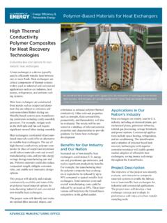
4 The essential mechanical components of the Otto-cycle and Diesel-cycle are the same. Both use a cylindrical combustion chamber in which a close fitting piston travels the length of the cylinder. The piston con-nects to a crankshaft that transforms the linear motion of the piston into the rotary motion of the crankshaft. Most engines have multiple cylinders that Power a single main difference between the two cycles is the method of igniting the fuel. Spark ignition engines (Otto-cycle) use a spark plug to ignite a pre-mixed air fuel mixture introduced into the cylinder. Compression ignition engines (Diesel-cycle) compress the air introduced into the cylinder to a high pressure, raising its temperature to the auto-ignition temperature of the fuel that is injected at high pressure. For CHP, most installations utilize 4-stroke spark ignition engines (see Figure 1).Reciprocating engines are characterized as either rich-burn or lean-burn. Rich-burn engines are operated near the stoichio-metric air/fuel ratio, which means the air and fuel quantities are matched for complete combustion, with little or no excess air.
5 In contrast, lean-burn engines are operated at air levels significantly higher than the stoichiometric ratio. In lean-burn engines, engine-out NOx emissions are reduced as a result of lower com-bustion chamber temperatures compared to rich-burn engines. Most spark ignition and diesel engines relevant to stationary Power generation applications complete a Power cycle in four strokes of the piston within the cylinder, as shown in Figure 1 stroke - introduction of air (diesel) or air-fuel mixture(spark ignition) into the Compression stroke - compression of air or an air-fuel mixturewithin the cylinder. In diesel engines, the fuel is injected ator near the end of the compression stroke (top dead center,or TDC) and ignited by the elevated temperature of thecompressed air in the cylinder. In spark ignition engines, thecompressed air-fuel mixture is ignited by an ignition source ator near Power stroke - acceleration of the piston by the expansion ofthe hot, high pressure combustion 1.
6 Four-stroke spark ignition reciprocating engine. Graphic credit IHS Exhaust stroke - expulsion of combustion products from thecylinder through the exhaust CharacteristicsPerformance characteristics for five representative natural gas reciprocating engines used in CHP applications are summarized in Table 2. The five systems shown in Table 2 range from 100 kW to MW, which covers most CHP installations that use reciprocating engines. Electric efficiencies generally increase with size, and the electric efficiencies for the five systems range from approxi-mately 30% (System #1) to 42% (System #5). Overall CHP effi-ciencies are near 80%, ranging from approximately 77% (System #5) to 83% (System #1). As electrical efficiency increases, the quantity of thermal energy available to produce useful heat decreases per unit of Power output, and the Power to heat ratio generally increases. A changing ratio of Power to heat impacts project economics and may affect the decisions that customers make in terms of CHP acceptance, sizing , and the desirability of selling Power .
7 For the representative systems in Table 2, the Power to heat ratio ranges from to In Power genera-tion and CHP applications, reciprocating engines generally drive synchronous generators at constant speed to produce stead alternating current (AC) Power . As load is reduced, the heat rate of spark ignition engines increases and efficiency decreases. While gas engines compare favorably to gas turbines which typically experience efficiency decreases of 15 to 25 percent at half load conditions multiple engines may be preferable to a single large unit to avoid efficiency penalties where significant load reductions are expected on a regular MANUFACTURING OFFICE2 Capital and O&M CostsTable 3 shows representative capital costs for natural gas reciprocating engines used in CHP applications. The costs are average values based on data collected from multiple manufac-turers. Installed costs can vary significantly depending on the scope of the plant equipment, geographical area, competitive market conditions, special site requirements, emissions control hardware, and prevailing labor rates.
8 Capital costs for generator set packages shown in Table 3 include all expenses for a complete CHP system, including heat recovery hardware and emission control equipment. The CHP systems shown in Table 3 are assumed to produce hot water, although recip-rocating engines are also capable of producing low pressure steam. With construction and installation included, installed costs range from $2,900 to $1,430 per kW. As indi-cated, capital costs decline on a per kW basis as size increases. Non-fuel operation and maintenance (O&M) costs are also shown in Table 3. As indicated, these costs range from to /kWh. Like capital costs, O&M costs decline as capacity increases. Maintenance costs vary with type, speed, size, and number of cylinders of an engine. These costs typically include: Maintenance labor Engine parts and materials ( , oil filters, air filters, spark plugs, gaskets, valves, piston rings, electronic components, etc.) and consumables, such as oil Minor and major overhaulsMaintenance can either be done by in-house personnel or contracted out to manufacturers, distributors, or dealers under service 2.
9 Reciprocating Engine Performance CharacteristicsDescriptionSystem12345 Net Electric Power (kW)3 1006331,1413,3259,341 Fuel Input (MMBtu/hr, HHV) Thermal (MMBtu/hr) to Heat Ratio5 Efficiency (%, HHV) 6 % Efficiency (%, HHV) Efficiency (%, HHV) : Performance characteristics are average values and are not intended to represent a specific Parasitic electric loads for reciprocating engines are typically small. In this fact sheet, parasitic loads are assumed to be negligible, resulting in no difference between gross and net Values in this fact sheet are based on the higher heating value (HHV) of natural gas unless noted otherwise. 5 Power to heat ratio is the electric Power output divided by the useful thermal 3. Reciprocating Engine Capital and O&M CostsDescriptionSystem12345 Net Electric Power (kW)1006331,1413,3259,341 Engine TypeRich-burnLean-burnLean-burnLean-burn Lean-burnEngine and Generator ($/kW, including heat recovery and emission control)$1,650$1,650$1,380$1,080$900 Construction and Installation$1,250$1,190$990$720$530 Total Installed Cost$2,900$2,840$2,370$1,800$1,430 Total O&M Cost ( /kWh) : Costs are average values and are not intended to represent a specific MANUFACTURING OFFICE3 EmissionsEmissions of criteria pollutants oxides of nitrogen (NOx), carbon monoxide (CO), and volatile organic compounds (unburned, non-methane hydrocarbons, or VOCs) are the primary environmental concern with reciprocating engines operating on natural gas.
10 Table 4 shows representa-tive emissions for reciprocating engines operating on natural gas in CHP applications. Emissions can vary significantly between different engine models and manufacturers and can also vary significantly with small changes in operating conditions ( , air/fuel ratio). Rich-burn engines have higher uncon-trolled NOx emissions com-pared to lean-burn engines and are almost always supplied with a three-way catalyst to control NOx, CO, and VOC emissions. For lean-burn engines, selective catalytic reduction (SCR) can be used to reduce NOx emis-sions if needed, and an oxida-tion catalyst can be used to reduce CO and VOC emissions. Table 4 shows CO2 emissions for CHP systems based on the Power output of the complete CHP system. For the complete CHP system, CO2 emissions are calculated with a thermal credit for natural gas fuel that would otherwise be used by an on-site boiler. With this thermal credit, CO2 emissions range from 452-536 lbs/MWh.