Transcription of Common Errors in Truss Design-10-31-17 - mitek-us.com
1 Page 1 of 15 Common Errors in Truss Design 4/24/2020 In today s competitive world of trusses, component manufacturers are always looking for ways to generate more efficient Truss designs. Occasionally, Truss designs need to be changed in order to be sealed and the objective of this document is to avoid Truss design parameters that are sent to engineers to be designed and sealed, but then must be changed. The following is a list of some of the most Common problems MiTek engineers see when reviewing customer Truss submittals. 1. Wrong building or wind codes. Be familiar with what building code your state requires and be sure to use a wind code compatible with the building code you are using. IBC2006 / IRC2006 and IBC2009 / IRC2009 Codes are based on ASCE 7-05, Minimum Design Loads for Buildings and Other Structures.
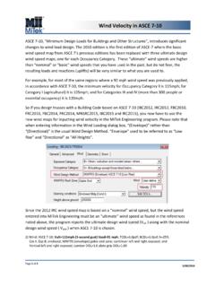
2 IBC2012 / IRC2012, FBC2010 / FRC2010, FBC2014 / FRC2014, IBC2015 / IRC2015 and MNSRC2015 are based on ASCE 7-10, Minimum Design Loads for Buildings and Other Structures . ASCE 7-10 edition was the first edition of ASCE 7 where the wind speed maps are based on the occupancy category and which provides ultimate wind speed. These ultimate wind speeds are higher than basic wind speeds from previous editions of ASCE-7. For example, according with ASCE 7-10 the minimum velocity for Occupancy Category II, is 115mph; Category I (agricultural) 105mph; and Categories III and IV (more than 300 people or essential occupancy) is 120mph for most of the same regions where 90 mph wind speed previously applied. If you design trusses with a building code based on ASCE 7-10 you have to use these wind maps for inputting wind velocity in the MiTek Engineering program.
3 If you design trusses with a building code based on ASCE 7-16, IBC-2018 or IRC-2018, input of the correct wind speed may get even more confusing as ASCE 7-10 wind maps and wind speeds are updated in ASCE 7-16. There are significant changes to the contours and wind speeds. To help you determine what wind speed to use for various locations, please visit the Helpful Resources section of our website, located on the bottom of page in Resources Engineering Engineering Support: The Applied Technology Council s (ATC) Wind Speed by Location is free of charge web-based tool that may be used to access wind speed data for various locations. Page 2 of 15 Common Errors in Truss Design 4/24/2020 2. Multiple-Ply Connections. Multiply girders perform according to the design only if all plies are properly attached together.
4 Be sure it is possible to transfer loads from one ply to the next on girder trusses. When we have load applied to a multiply girder Truss , in order to design the fasteners, we assume all plies take an equal amount of load. If fasteners required to distribute loads equally between plies cannot be calculated by software, the warning Special connection required to distribute bottom chord / top chord / web loads equally between all plies or Ply to ply nailing inadequate will appear in the note section of the Truss design drawing. If you have a vertical web directly above large concentrated load, you can try to use this vertical to transfer load. To turn it on in MiTek 20/20 Engineering go to Design Info - Nails/Screws/Bolts, check the Use verticals for load distribution box as shown below: In Structure with Truss Design in Properties dialog box select Roof Fastener Settings , change to Yes in Is Unique to Truss in General section and to Yes in Use verticals for load distribution in Connection Options section as shown below: After selection is made, Redesign the Truss .
5 If ply-to-ply connection note does not go away, try changing the type of nail or fastener you are using. Structural screws can transfer more load than nails. The length of the fasteners used to make ply-to-ply connections should not exceed the thickness of the multiple-ply Truss . If these options do not fix the problem, submit the Truss to your MiTek Design Engineer for help. Page 3 of 15 Common Errors in Truss Design 4/24/2020 3. Bearing undersized. The first thing to consider with bearing sizes is the minimum required by the building codes. The minimum bearing size is 1-1/2 inches. MiTek engineering software calculates minimum bearing size, based on default bearing material and compares it with bearing size input by the Truss Designer. So, it is important to specify the actual bearing sizes for the Truss .
6 When the minimum required bearing size exceeds the input bearing size, the warning Required bearing size at joint(s).. greater than input bearing size in the general note section of the Truss Design Drawing is displayed. This warning should not be neglected by the Truss Designer. This warning is due to the bottom chord and/or top plate crushing from the reaction of the Truss . One way to correct this problem is to click on Bearing Design Options, and check any of the options available. To turn it on in MiTek 20/20 Engineering go to Design Info Bearing Design Options. In Structure with Truss Design, in the Properties dialog box select Roof/Floor Bearing Options , and after you change to Yes in Is Unique to Truss in General section, click on the drop-down menu of Bearing Design Options. These options include upgrading lumber, using a bearing block, or using a Truss bearing enhancer.
7 If you have these options checked, the program will attempt to fix the undersized bearing problem. If the bearing is still too small you may need to either increase the actual size of the bearing or add a ply to the Truss . Bearing Design Options Bearing Options Settings in in MiTek 20/20 Engineering Structure with Truss Design When using the Bearing Block option to fix an undersized bearing, care must be taken on trusses with long scarf cuts at the heel. The Bearing Block ignores the scarf cut when calculating the nailing requirements. The nailing pattern and quantity of nails shown may be impossible to achieve. Also use caution with trusses tying into a girder Truss with bearing blocks.
8 If the location of a tie-in Truss interferes with the attachment of the bearing block, the bearing block may not be able to be used and Page 4 of 15 Common Errors in Truss Design 4/24/2020 other provisions for the bearing requirement may be needed. Note bearing blocks are assumed to be the same lumber grade and species as the bottom chord. If a vertical member comes down directly above a bearing, like a web at an interior bearing or at a raised heel, you may be able to run the vertical through the bottom chord, so the end grain of the vertical member is sitting directly on the bearing, which gives a much higher crushing value. Be aware this will fix the crushing on the Truss only and not the top plate of the wall. The program assumes you are using the same material on the top plate as the bottom chord of your Truss unless set up otherwise.
9 When in doubt, have these trusses reviewed by your MiTek Design Engineer. 4. Gable end trusses run as interior wind zone. If a Truss is at the end of the building, be sure the roof zone is set to exterior or gable end zone in the wind loading tab if applicable. Wind Loading Dialog Box in MiTek 20/20 Engineering Loading Wind Section in Building Code Settings in Structure with Truss Design Page 5 of 15 Common Errors in Truss Design 4/24/2020 5. Thermal factor needs to be selected correctly Thermal factors should only be set to if the roof trusses will be heated and kept above freezing at all times. This may occur in some commercial buildings where a drop ceiling is used. If drywall and/or insulation is being used on the bottom chord of the roof Truss (most residential) the thermal factor or Ct factor should be set to because the heat from the building will not escape into the enclosed Truss area.
10 For unheated agricultural buildings, a Ct factor of should be used. Snow Loading Dialog Box in MiTek 20/20 Engineering Loading Snow Section in Building Code Settings in Structure with Truss Design 6. Corner girders missing load. Many times, on cantilevered corner girders, you will need to make sure additional load for framing and fascia loads are added at the end of the girder or cantilevered section. Since framing is often used instead of trusses, layout does not put this additional load on the end of a corner girder. If a structural fascia is being used, a concentrated load will need to be added at the end of the corner girder and also at the end of the other Truss which will be supporting the other end of the fascia. For detail how this can be achieved for symmetric corners with Girder Loading in MiTek Engineering software please refer to Cantilever Corner Girder Loading Tool technical article on MiTek United States website in Resources -Engineering Technical Articles Helpful Design Tips.