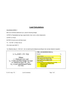
Transcription of Common Retaining Walls - About people.tamu.edu
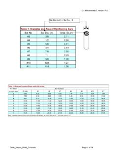
1 Dr. Mohammed E. Haque, Retaining Walls Page 1 Common Retaining Walls Toe Heel Gravity or Semi-gravity Retaining wall ToeHeel Cantilever Retaining wall Stem Footing ToeHeel Buttress Retaining wall Stem Footing Buttress ToeHeel Counterfort Retaining wall Stem Footing Counterfort Back Fill Back Fill Back Fill Back Fill Ground Level Ground Level Ground Level Ground Level Ground Level Ground Level Ground Level Ground Level Dr. Mohammed E. Haque, Retaining Walls Page 2 First Floor Basement Floor Footing Stem Basement Wall Foundation Ground Level Dr. Mohammed E. Haque, Retaining Walls Page 3 Bearing Plate Bridge Girder Back-wall Piles Pile Cap Bridge Abutment Ground Level Back Fill Dr. Mohammed E. Haque, Retaining Walls Page 4 External Stability of Cantilever Retaining Wall 1.
2 A Cantilever Retaining Wall must not slide horizontally Fig 1. Sliding Failure of Cantilever Retaining Wall Dr. Mohammed E. Haque, Retaining Walls Page 5 2. A Cantilever Retaining Wall must not overturn. Fig 2. Overturning Failure of Cantilever Retaining Wall Dr. Mohammed E. Haque, Retaining Walls Page 6 3. The resultant of the normal force at the base of footing must be within middle third of the width of footing. Middle third of L L R L/3 L/3 L/3 Dr. Mohammed E. Haque, Retaining Walls Page 7 4. The foundation must not experience a soil bearing capacity failure. Fig 4. Bearing Capacity Failure of Cantilever Retaining Wall Dr. Mohammed E. Haque, Retaining Walls Page 8 5.
3 The foundation must not experience a deep-seated shear failure. Fig 5. Deep-seated shear Failure of Cantilever Retaining Wall Dr. Mohammed E. Haque, Retaining Walls Page 9 6. The foundation must not experience an excessive settlement. Fig 6. Excessive settlement of Cantilever Retaining Wall Excessive settlement Dr. Mohammed E. Haque, Retaining Walls Page 10 Lateral Soil Pressure on Retaining Walls Typical Angle of Internal Friction for backfill soil Soil Type (Degree) Gravel and coarse sandy backfill soil 33-36 Medium to fine sandy backfill soil 29-32 Silty sand 27-30 P max = Ka soil h h soil Backfill Fig. 1: Soil Pressure on the back of wall (No surcharge) Ka = Coefficient of Active Soil Pressure Ka = tan2 (450 - /2) = Angle of Internal Friction for backfill soil soil = Unit weight of Soil (pcf) Dr.
4 Mohammed E. Haque, Retaining Walls Page 11 P max = Ka soil h h soil Backfill Fig. 2: Soil Pressure on the back of wall (Sloping Backfill) cos - (cos2 - cos2 ) cos + (cos2 - cos2 ) Ka = cos Dr. Mohammed E. Haque, Retaining Walls Page 12 P max = Ka soil h h soil Backfill Fig. 3: Soil Pressure on the back of wall (with uniform surcharge) Surcharge, wsc + Psc = Ka wsc Dr. Mohammed E. Haque, Retaining Walls Page 13 Q1(a): Analyze the stability of the reinforced cantilever Retaining wall as shown in Figure. Use the following values: Concrete unit weight = 150 pcf Soil unit weight, soil =110 pcf Coefficient of Active Soil Pressure, Ka = (Neglect Coefficient of passive Soil Pressure, Kp) Coefficient of friction between the bottom of footing and soil, = 10 2 2 2 1 4 Dr.
5 Mohammed E. Haque, Retaining Walls Page 14 Solution: Step 1: Calculate lateral soil pressure and overturning moment P max = Ka soil h = (110)(12) = psf FH = Pmax h = ( )(12)= lb/ft of wall Sliding Force, FH = lb/ft of wall Overturning Moment, MOT About toe = x 4 = lb-ft /ft of wall. 12 2 2 2 1 4 Wsoil Wwall WFooting FH Pmax Toe A 5 1/3(12 )=4 Dr. Mohammed E. Haque, Retaining Walls Page 15 Step 2: Calculate weights, Resisting Moment, Sliding Resisting Force; Wsoil = (4 x 10)(110) = 4400 of wall Wwall = (1 x 10)(150) = 1500 lb / ft of wall WFooting = (2 x 7)(150) = 2100 lb / ft of wall WTotal = 4400 + 1500 + 2100 = 8000 lb / ft of wall Resisting moment , MR About toe = (4400 x 5) + (1500 x ) + (2100 x ) = 33100 lb-ft/ft of wall Sliding Resisting Force, FR = X WTotal = (8000) = 4000 lb Step 3: determining the Factor of Safety (FS) against overturning and sliding.
6 FS OT = MR / MOT = 33100 / = > OK FS Sliding = FR / FH = 4000 / = > OK Dr. Mohammed E. Haque, Retaining Walls Page 16 Soil Pressure under the footing of the Retaining Wall f = fmax = P/A = P/(Bx1) B P= WTotal c= B/2 Case I: Load, P with zero eccentricity (e=0) fmax = P/A + (P e /Sm) fmin = P/A - (P e /Sm) where A= 1xB Sm = 1x(B2)/6 B P= WTotal c > B/3 Case II: Load, P with small eccentricity (e<B/6) e<B/6 fmax fmin fmax = (2/3)P/c B P= WTotal c B/3 Case III: Load, P with large eccentricity (e B/6) e B/6 fmax Dr. Mohammed E. Haque, Retaining Walls Page 17 Q1(b) Calculate the soil pressure under the footing of the Retaining wall of Q1(a). Determine the resultant vertical force, WTotal intersects the bottom of the footing: c = (MR MOT)/ WTotal = (33100 - ) / 8000 = ft.
7 From the Toe. Eccentricity, e = B/2 c = (7/2) = < B/6 (=7/6= ) Therefore, Case II is applicable. Calculate soil pressures, fmax and fmin under the footing: A= 1xB = 7 sqft. Sm = 1x(B2)/6 = 72 / 6 = ft3 P= WTotal = 8000 lb. fmax = P/A + (P e /Sm) = (8000/7) +( ) = + = psf fmin = P/A - (P e /Sm) = = - = psf of Footing c= 2 fmin WTotal B=7 Toe e fmax Dr. Mohammed E. Haque, Retaining Walls Page 18 Groundwater effects If the groundwater table rises above the bottom of wall footing (Fig b), following three important changes occur: 1. The effective stress in the soil below the groundwater table will decrease, which decreases the soil active, passive, and at-rest pressures. 2. Horizontal hydrostatic pressure due to groundwater will act against the wall, and will be added to lateral earth pressure.
8 3. The increased hydrostatic pressures (item 2 above) more than offset the decreased effective stress (item 1 above), and the net effect is a large increase of total horizontal pressure acting on the wall (Fig b). 4. The effective stress between the bottom of the footing and soil will decrease, which decreases sliding frictional resistance. Groundwater Table Groundwater Table (a) Groundwater Table at or below the bottom of footing (b) Groundwater Table above the bottom of footing Lateral pressure due to backfill Backfill soil Backfill soil Hydrostatic pressure Lateral pressure due to backfill