Transcription of Communication Quick 2. SETTING RS-485 …
1 Digital Temperature Controller IMR02C41-E2 Thank you for purchasing this RKC product. In order to achieve maximum performance and ensure proper operation of your new instrument, carefully read all the instructions in this manual. Please place the manual in a convenient location for easy reference. This manual describes the connection method with host computer, Communication parameters and Communication data (except for parameters in engineering mode) of the RB100/400/500/700/900. 1.
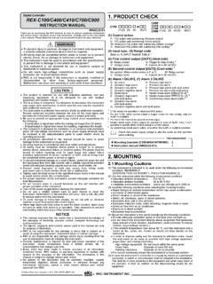
2 CONNECTION TO HOST COMPUTER Make sure that lugs or unshielded cables of the Communication terminals are not touched to the screw heads, lugs, or unshielded cables of the power supply terminals to prevent electric shock or instrument failure. Use additional care when two lugs are screwed to one Communication terminal. The cable must be provided by the customer. Communication Terminal Number and Signal Details Terminal No. RB100/400/500/900 RB700 Signal name Symbol 13 25 Signal ground SG 14 26 Send/Receive data T/R (A) 15 27 Send/Receive data T/R (B) Wiring Method When the interface of host computer (Master) is RS-485 Host computer (Master) RS-485 y y y Paired wire Shielded twisted pair wire Controller (Slave) *R *R T/R (B) T/R (A) SG T/R (B) T/R (A) SG ( ) (+) Controller (Slave)
3 T/R (B) T/R (A) SG ( ) (+) ( ) (+) Screw size: M3 7 (with square washer) Recommended tightening torque: N m (4 kgf cm) Specified solderless terminals: Manufactured by MFG CO., LTD. Circular terminal with isolation (M3 screw, width mm, hole diameter mm) *R: Termination resistors (Example: 120 1/2 W) Maximum connections: Up to 31 instruments 13 (25) 14 (26) 15 (27) 13 (25) 14 (26) 15 (27) When the host computer (Master) has a USB connector Connect the USB Communication converter between the host computer and the controller.
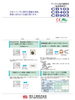
4 RS-485 y y y Paired wire Shielded twisted pair wire Controller (Slave) *R T/R (B) T/R (A) SG ( ) (+) Controller (Slave) T/R (B) T/R (A) SG Host computer (Master) USB Communication converter COM-K (RKC product) Connect to USB port USB cable(COM-K accessory)Connect to USB connector of COM-K The termination resistor is built into the COM-K. 1 SG 2 4 3 5 T/R (A) T/R (B) Unused Unused ( ) (+) Screw size: M3 7 (with square washer) Recommended tightening torque: N m (4 kgf cm) Specified solderless terminals: Manufactured by MFG CO.
5 , LTD. Circular terminal with isolation (M3 screw, width mm, hole diameter mm) *R: Termination resistors (Example: 120 1/2 W) Maximum connections: Up to 31 instruments 13 (25) 14 (26) 15 (27) 13 (25) 14 (26) 15 (27) For the COM-K, refer to the COM-K Instruction Manual (IMR01Z01-E ). 2. SETTING To establish Communication parameters between host computer and controller, it is necessary to set the following parameters. When all Communication parameter settings have been completed, turn the power off and then on to make the new set values take effect.
6 This instrument returns to the PV/SV monitor screen if no key operation is performed for more than 1 minute. This section describes the parameters which must be set for Communication . For the mode/parameters transfer and data SETTING , refer to the RB series Quick Operation Manual (IMR02C39-E ) and RB series Parameter List (IMR02C40-E ). Description of each parameters (Engineering mode F60) Symbol Name Data range Description Factoryset value (F60.)
7 Function block 60 This is the first parameter symbol of Function block 60. (CMPS) Communication protocol 0: RKC Communication 1: Modbus Use to select a protocol of Communication function. Dependson model code (Add) Device address (Slave address) 0 to 99 (Modbus: 1 to 99) Do not use the same device address for more than one instrument in multi-drop connection. 0 (Modbus: 1) (bPS) Communication speed 0: 2400 bps 1: 4800 bps 2: 9600 bps 3: 19200 bps Set the same Communication speed for both the controller (slave) and the host computer (master).
8 3 (bIT) Data bit configuration Refer to Data bit configuration table Set the same Data bit configuration for both the controller (slave) and the host computer (master). 0 (INT) Interval time 0 to 250 ms The Interval time for the controller should be set to provide a time for host computer to finish sending all data including stop bit and to switch the line to receive status for the host. 10 Data bit configuration: Set value Databit Parity bit Stop bit Settable Communication Set value Databit Paritybit Stopbit Settable communication0 8 Without 1 6 7 Without1 1 8 Without 2 7 7 Without2 2 8 Even 1 8 7 Even1 3 8 Even 2 9 7 Even2 4 8 Odd 1 10 7 Odd1 5 8 Odd 2 RKC Communication Modbus 11 7
9 Odd2 RKC Communication Interval time: The Interval time for the controller should be set to provide a time for host computer to finish sending all data including stop bit and to switch the line to receive status for the host. If the Interval time between the two is too short, the controller may send data before the host computer is ready to receive it. In this case, Communication transmission cannot be conducted correctly. 3. Communication REQUIREMENTS Processing times during data Send/Receive When the host computer is using either the polling or selecting procedure for Communication , the following processing times are required for controller to send data: - Response wait time after controller sends BCC in polling procedure - Response wait time after controller sends ACK or NAK in selecting procedure Response send time is time when Interval time is set at 0 ms.
10 RKC Communication (Polling procedure) Procedure details Time Response send time after controller receives ENQ 60 ms max. Response send time after controller receives ACK 60 ms max. Response send time after controller receives NAK 60 ms max. Response send time after controller sends BCC 52 ms max. RKC Communication (Selecting procedure) Procedure details Time Response send time after controller receives BCC 65 ms max. Response wait time after controller sends ACK 52 ms max. Response wait time after controller sends NAK 52 ms max. Modbus Procedure details Time Read holding registers [03H] Response send time after the slave receives the query message 60 ms max.