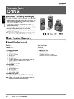
Transcription of Compact Interlock Safety Door Switch D4DS
1 1 Compact Interlock Safety Door SwitchD4 DSCompact Safety Switch Saves Spaceand is Ideal for a Variety of DoorsPositive opening mechanism and doubleinsulation approved by T V and Operation by UL, CSA, BIA, and SUVA ratings: IP65 (EN60529), Type 4(UL/CSA) (indoor use only).Refer to Precautions on page :AgencyStandardFile VRheinlandEN60947-5-1(positive opening)R9551708UL (see note)UL508 CSA ,EN60947-5-11-conduit:95099152-conduit:9 509913 SUVASUVA1- :CSA No. 14 compliance was verified and approvedby UL (Marked with ).
2 Conformity:Machine DirectiveLow-voltage DirectiveprEN1088C ULD4 DSD4DS2 Ordering InformationModel Number (1-conduit)2:G1/2 (1-conduit)3:1/2-14 NPT (1-conduit)5 (2-conduit)6:G1/2 (2-conduit) Switch5:1NC/1NO (Slow-action)A:2NC (Slow-action) Mounting DirectionF:Front-side Key Type1:Horizontal mounting2:Vertical mounting3:Adjustable mounting(horizontally adjustable) d4ds -Kj1 Operation KeyD4DS-jjjj1234 Note:Note that any order for the head part or the Switch part alone cannot beaccepted. The Operation Key is sold size1NC/1NO (Slow-action)2NC (Slow-action)Positive openingModelPositive Accessories (Order Separately)Operation KeyMounting typeModelHorizontalD4DS-K1 VerticalD4DS-K2 Adjustable(horizontal) d4ds -K3D4 DSD4DS3 Specifications RatingsApplicable StandardsT V and BIA (EN60947-5-1)Utilization categoryAC-15 Rated operating current (Ie)2 ARated operating voltage (Ue)400 VUL (UL508/CSA )
3 A600 Rated voltageCurrentVoltage S AmpereContinuousMakeBreakMakeBreak120 VAC10 A60 A6 A7,200 VA720 VA240 VAC30 A3 A480 VAC15 A600 VAC12 AGeneralRated voltageNon-inductive loadInductive loadResistive loadLamp loadInductive loadMotor loadNCNONCNONCNONCNO125 VAC10 A3 A10 A5 A250 VAC10 A2 A1 A10 A3 A400 VAC10 A3 A8 VDC10 A6 A3 A10 A6 A14 VDC10 A6 A3 A10 A6 A30 VDC6 A4 A3 A6 A4 A125 A250 ANote:The above current ratings are for a steady-state load has a power factor of min.
4 (AC) and a time constant of 7 ms max. (DC).Lamp load has an inrush current of 10 times the steady-state load has an inrush current of 6 times the steady-state CharacteristicsOperating m/s to m/sContact gap2 x 2 mm frequency30 operations/minInsulation resistance100 M min. (at 500 VDC) between terminals of same polarity, between terminals ofdifferent polarity, between each terminal and ground, and between each terminal andnon-current-carrying metal partContact resistance25 m max. (initial value)Dielectric strengthUimp 4 kV between terminals of same polarity, between terminals of different polarity,between each terminal and ground, and between each terminal and non-current-carryingmetal part (EN60947-5-1)Rated insulation voltage (Ui)400 V (EN60947-5-1)Switching overvoltage1,500 V max.
5 (EN60947-5-1)Pollution degree(operating environment)3 (EN60947-5-1)Short-circuit protective device (SCPD)10 A, fuse type gI or gG (IEC269)Conditional short-circuit current100 A (EN60947-5-1)Conventional enclosed thermal current(Ithe)10 A (EN60947-5-1)Protection against electric shockClass II (double insulation)Vibration resistanceMalfunction:10 to 500 Hz, single amplitude with an imposed acceleration of100 m/s2 (10G) resistanceDestruction:1,000 m/s2 min. (approx. 100G min.)Malfunction:300 m/s2 min.
6 (approx. 30G min.)Life expectancy (see note 1)Mechanical:1,000,000 operations :150,000 operations temperatureOperating: 30 C to 70 C (with no icing)Ambient humidityOperating:95% rating (see note 2)IP65 (EN60947-5-1)WeightApprox. 76 g (for d4ds -15FS)Note:The above mechanical life and electrical life are possible when the ambient temperature is 5 C to 55 C and the ambient humidity is40% to 70%.Although the Switch casing resists dust, oil, and water, make sure that the keyhole on the head is free from dust, oil, water, andchemical, otherwise the d4ds may wear out, break, or malfunction.
7 Operating CharacteristicsOperating force (extraction) N (3,000 gf)Release force (insertion) N (1,500 gf)Pretravel6 3 mmTotal travel (reference value)28 mmMin. positive opening force (see note) N (6,000 gf)Min. positive opening stroke (see note)10 mmNote:Make sure that the positive opening stroke is at least 10 mm in order to use the d4ds KeyThe dedicated key prevents operational mistakes and forci-bly separates the head can be mounted in four directions. The Opera-tion Key can be inserted in five directions including thedownward cover, with a hinge on its lower part, can be openedby removing the screw of the cover, which ensures easeof maintenance and SwitchHas a positive opening mechanism which forcibly separatesthe NC contacts even if they are built-in Switch incorporates a pair each of NC contactsand NO contacts or two pairs of NC Switch :1-conduit, 2-conduit modelsG1/2:1-conduit, 2-conduit models1/2-14 NPT.
8 1-conduit modelsOil SealThe plunger has an O ring. The Switch casing ensuresIP65 (except the keyhole, which ensures IP00). Use theD4DS in places where the keyhole is free from oil andmetal :The housing and head of the d4ds are made of synthetic resin. If highmechanical durability is required, use the D4BS Safety Door Contact FormModelContactDiagramsRemarksD4DS-j5jS 1NC/1NO11122324Zb11 to 1223 to 24 StrokeONInsertionpositionFully-drawnposi tionOnly NC contacts 11 and 12 have anapproved positive to 1221 to 22 StrokeONInsertionpositionFully-drawnposi tionNC contacts 11, 12, 21, and 22 havean approved positive :Terminals are numbered according to EN50013 and contacts are marked according to EN60947-5-1.
9 Positive Opening Mechanism1NC/1NO Contact (Slow-action)2NC Contact (Slow-action)Contact springReturn springFixed contact (NC)Movable contactPlungerFixed contact (NO)Contact springReturn springFixed contact (NC)Movable contactPlungerOnly the NC contacts have a positive open-ing metal deposition occurs, the contactsare separated from each other by pushing inthe to EN60947-5-1 Positive OpeningBoth NC contacts incorporate a positiveopening metal deposition occurs, the contactsare separated from each other by pushing inthe to EN60947-5-1 Positive OpeningNote:The switches are marked with indicating approval for the positive opening.
10 All units are in millimeters unless otherwise otherwise specified, a tolerance of mm applies to all conduit thread varies with the model as follows:Conduit ModelsD4DS-1jjSD4DS-2jjSD4DS-3jjS2-condu it ModelsD4DS-5jjSD4DS-6jjSSee note 3on page holesdepth: 5 Two, 4+ holes30 x 3030 x 30 Capdepth: 5 Two, 4+ holes56 holesSee note 3on page KeysD4DS-K1D4DS-K2D4DS-K3 Four, , Operation Key InsertedD4DS-1jjS + d4ds -K1D4DS-2jjS + d4ds -K1D4DS-3jjS + d4ds -K1D4DS-5jjS + d4ds -K1D4DS-6jjS + d4ds -K1D4DS-1jjS + d4ds -K2D4DS-2jjS + d4ds -K2D4DS-3jjS + d4ds -K2D4DS-5jjS + d4ds -K2D4DS-6jjS + d4ds -K2D4DS-1jjS + d4ds -K3D4DS-2jjS + d4ds -K3D4DS-3jjS + d4ds -K3D4DS-5jjS + d4ds -K3D4DS-6jjS + d4ds -K344 to insertion faceHorizontal keyinsertion radiusR y 200 Permissible differencein center lines betweenthe Operation Key andkey to insertion facePermissible differencein center lines