Transcription of Comparative study for cables and busbars - zucchini.com.mx
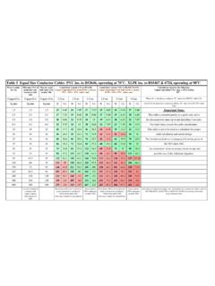
1 Comparative study on cables and busbars page 1 Comparative study for cables and busbarsPreliminary considerationsTo compare the prices of two categories of product as different as traditional cables and busbars , it is necessary tomake some preliminary considerations based on actual cases, particularly as regards calculating the actual cost the price of cable depends on the price of the raw materials. Here we have taken the price of copper as4700 lire per are quoted as if they refer to an offer for an end user of average importance for building a prices for busbars , cables and cable ducts are calculated as the average of prices provided by severalmajor companies dealing in wiring busbar is defined by CEI EN 60439-2 as a type-tested assembly (TTA) comprising a system of conductorswith one or more bars separated and supported by insulating material and contained in a conduit or similarcasing.
2 Zucchini busbars are assemblies that have been type-tested (TTA) and comply with IEC 439/1 and IEC 439/2product standards and the corresponding harmonised Italian standards CEI EN 60439-1 and CEI EN , from among the vast range of Zucchini busbars we have selected the series of Armoured Ventilated Bars(AVB) for places not requiring a high short-circuit current and where there are no major problems of space, andthe Super Compact (SC) line where a high short-circuit current, compact size and a high degree of protection(IP55) are cablesThe sizing of power cables must be done very carefully. They must be built according to CEI 20-14, CEI 20-22/2and CEI 20-37 product capacity of the cables is greatly affected by the type of installation, which determines the effectiveness of heatdissipation, and reactance depends on their reciprocal factors for the different types of installation, particularly for close grouping as in our example, aretaken from Table C, CEI 64-8, part 5, 4th comparison only takes into account cables laid in perforated ducts, which ensure good ventilation and hencegood heat that CEI 64-8 considers cables as laid in the air if at least 30% of the surface of the tray supporting themis perforated.
3 At present the only tray on the market meeting these requirements are the wire cables used in this comparison are PVC insulated, which means the copper they contain can withstandtemperatures of up to 70 reasons of cost, ease in procuring materials and assembly, we decided not to use multi-pole cables greaterthan 185 mm2 or single-pole cables greater than 240 study on cables and busbars page 2 Comparison of power supply costs for a medium- size metal working low-voltage switchboard connectionThe cost of connecting the transformer and switchboard depends mainly on two factors:1. the rated power of the transformer2. the wiring layoutTo make a reliable cost estimate, it is necessary to consider actual us examine two typical situations:In the first case we have a connection between a transformer and a low-voltage switchboard that is short andstraight (see Figure 1).
4 Figure 1: Straight connection between transformer andlow-voltage ) accumulator room; 2) low-voltage switchboard;3) high-voltage switchboard; 4) transformer; 5) of the wiring system starts by calculating the power required to run the factory in question. Whencalculating installed power, it is necessary to consider the contemporary load coefficient, the utilisationcoefficient, the average cos of loads, and a convenient upscale coefficient taking into account possible extensionto the system. When the installed power has been calculated, you can select the most suitable size of transformerfor the , presuming that the link between the transformer and low-voltage switchboard is short and straight, we canprove that the cost depends only on the power of the 2. Ratio for busbar and cable connection study on cables and busbars page 3 The graph in figure 2 shows the cost ratio between connections busbars and the traditional but often obsolete method using power the cost for cable connection as 100, we can see for each size of transformer that the cost of a cableconnection increases with the size of transformer, and cost parity (materials plus installation) is reached for a 1000kVA the second example, let us suppose that for reasons of system reliability and flexibility the factory hasdecided to install three transformers and the connection between transformers and switchboard has at least twohorizontal, rather than straight, 3.
5 Complex connection between three transformers and low-voltage ) transformers; 2) busbar; 3) low-voltage the second example here, the cost ratio between connecting with busbars and cables has a similar trend to theprevious example, but cost parity is reached for smaller transformers (see Figure 5).Figure 4. Transformer- switchboard connection. The problems in connecting a bundleof cables and the transformer terminal and switch are study on cables and busbars page 4 Figure 5. Ratio between the cost of a complex transformer- switchboard connection using busbars and a wiring system in a 15-storey office blockLet us suppose we have to design a wiring system in a 15-storey office block and we need to power utilities ratedat the floors are supplied via a single shaft. Each floor needs a control panel with a knife switch and fuse holder(or a thermalmagnetic circuit breaker) to protect and cut off the system for the entire floor.
6 In our example, theswitchboard supplying the various floors via the shaft is not in the immediate vicinity of the shaft, it is about 30metres from the base of means three different systems can be considered:1 . The entire system can use busbars , link the switchboard-shaft and the 15-floor riser using a prefabricated system of . Alternatively, the low-voltage switchboard and the riser power supply box can be connected using busbars with a bundle of suitably sized cables , and the riser alone using . Lastly, the entire system can be laid with power cables . This means that the same number of bundles of cablesas floors in the building will have to run from the switchboard and each bundle will have to run up the shaft vertically, stopping at its own floor, so the number of bundles decreases the further up you let us examine the advantages and disadvantages of these three.
7 BusbarsA study of the power for each floor shows that the capacity of the busbar must be 1000 A. Where the busbarleaves the low-voltage switchboard, it is protected by a thermalmagnetic circuit breaker. As the busbar runs the 30metres to the shaft, it passes through the boiler and air-conditioning rooms and then runs up the shaft vertically tothe top floor (see Figure 6).There is a tap-off at each floor to supply the utilities on that floor. Flame barriers can be situated along the shaft atthe various floor levels to prevent the spread of fire, smoke and heat if a fire should break out on a lower study on cables and busbars page 5 Figure 6. Switchboard-transformer link using 1000 A busbars powered at both . Mixed cable /busbar layoutFigure 7 shows a mixed layout for the system supplying power to the various floors in the building.
8 It takes four3 x 185/95 mm2 multi-pole cables in parallel to supply the 1000 A busbar riser with a cable link. This bundle ofcables connects with the busbar via the switchboard at the front end. To supply the riser, the cables too need topass through the heating, cooling and ventilation rooms, so steps must be taken to prevent toxic and corrosivegases from spreading through the building from the air conditioning plant in the event of a fire. Alternatively, cables with a low emission of gas and toxic agents must be 7. Mixed cable /busbar linkComparative study on cables and busbars page 63 . cable layoutFigure 8 shows the power supply to the various floors of the building with a bundle of cables each from theswitchboard to its own substation at each floor. The cables used are multi-pole, section 3 x 50/25 mm2.
9 Theswitchboard needs to have as many circuit breakers as the outputs (15), or alternatively the individual cables canbe 8. Switchboard floor substation link with 3 x 50/25 mm2 cablesFlexibility of the different types of systemWhen calculating ratings, designers generally take into consideration a convenient upscale coefficient for futureextensions to the building. So with cables it will be necessary to oversize all the system s cables at the outset. Forobvious economic reasons, this coefficient will only take into account the probability of a slight increase in loadpower. If the power increases excessively, the transformer supplying the building will have to be replaced orpaired with another transformer. With the use of busbars , later extensions do not involve many technical we suppose that the absorbed power at each floor in the building increases by about 10%, the power of themain transformer is no longer enough to meet demands, so in this case the best technical and economic solution isto install another transformer of a suitable capacity.
10 The new transformer will only have to be connected to thebusbar from the top of the riser (top floor). Thus in this case it will only be necessary to pass one cable along theshaft to supply the busbar on the other side. This solves the problem easily and us now consider the more common case in which total power required by the building is constant, butdivision between the floors varies. In the cable solution it is necessary to check that the various cables supplyingthe floors of the building can withstand the new load and if necessary add another cable in parallel if the powerexceeds the capacity of the cable . With the busbar solution, this will not be necessary thanks to the flexibility ofthe system. At most, it will be necessary to change the protection device of the cable from the switchboard to thefloor substation - only a few metres of study on cables and busbars page 7 Figure 9.