Transcription of Comparative study of P, PI and PID controller for speed ...
1 2014 IJEDR | Volume 2, Issue 2 | ISSN: 2321-9939. Comparative study of P, PI and PID controller for speed control of VSI-fed induction motor 1. K Smriti Rao, 2 Ravi Mishra 1. Research Scholar, 2 Assistant Professor SSTC Bhilai, Chhattisgarh, India _____. Abstract This paper has been attempted to presents the Comparative study of Proportional (P), Proportional Integral (PI), and Proportional Integral Derivative(PID) controller for speed control of induction motor. In general, the principle of operating a three phase IM indicates that the speed of the motor is directly related to the frequency of the supply. This fact has made the inverter fed induction motor having a very common configuration in the majority of industrial applications. The VSI-fed IM drives are increasingly applied in many recent industrial applications that require excellent transient performance of drives.
2 Better performance of P, PI and PID controller is studied and compared. _____. I. INTRODUCTION. Everyone recognizes the vital role played by electrical motors in the development of industrial systems. Induction motors are today a standard for industrial electrical drives and high performance variable speed drive application have a series of advantages. There are several ways for speed control of IMs fed through the VSIs using different modulation techniques. Researchers, scientist and engineers are continuously inventing the new techniques and methods that cover the speed control requirements of the drive. Advanced control techniques such as fuzzy, neuro-fuzzy, genetic algorithm, sliding mode control , etc. have also been extensively used in motion control applications. Inherently straightforward operating characteristics, flexible performance and efficiency encouraged the use of VSI-fed induction motors in many types of industrial drive application.
3 Most multi-purpose production machines benefit from adjustable speed control , since frequently their speeds must change to optimize the machine process or adapt it to various tasks for improved product quality, production speed . VSIs are used to regulate the speed of three-phase squirrel cage IM (SCIM) by changing the frequency and voltage and consist of input rectifier, DC link and output converter. They are available for low voltage range and medium voltage range. The basic action involved in adjustable speed control of IM is to apply a variable voltage magnitude, and variable frequency to the motor so as to obtain variable speed operation. Both the VSI and Current Source Inverter (CSI) are used in adjustable speed AC drives. shows the block diagram of VSI-fed induction motor drive using P, PI and PID controller . II.
4 FUNDAMENTALS OF CONVENTIONALCOTROLLERS SUCH AS P, PI AND PID controller . PID controllers use a 3 basic behavior types of modes: P-proportional, I- integral and D- derivative. While Proportional and integrative modes are also used as single control modes a derivative mode is rarely used on it's own in control systems. Such combinations such as PI and PID controller are very often in practical systems (A) Proportional (P) controller A P controller system is a type of linear feedback control system. The P controller system is more complex than on-off control systems like a bi-metallic domestic thermostat, but simpler than a PID control system used in something like an automobile cruise controlIn general it can be said that P controller cannot stabilize higher order processes. For the 1st order processes, meaning the processes with one energy storage, a large increase in gain can be tolerated.
5 IJEDR1402230 International Journal of Engineering Development and Research ( ) 2740. 2014 IJEDR | Volume 2, Issue 2 | ISSN: 2321-9939. Proportional controller can stabilize only 1st order unstable process. Changing controller gain K can change closed loop dynamics. A large controller gain will result in control system with: a) Smaller steady state error, better reference following b) Faster dynamics, broader signal frequency band of the closed loop system and larger sensitivity with respect to measuring noise c) Smaller amplitude and phase margin Block diagram of P controller In the P controller algorithm, the controller output is proportional to the error signal, which is the difference between the set point and the process variable. In P controller the actuating signal for the control action in a control system is proportional to the error signal.
6 The error signal being the difference between the reference input signal and feedback signal obtained from the output. For the system considered as shown in the Fig. 5. The actuating signal is proportional to the error signal therefore; the system is called P controller system. The error of signal given as follows: e(t) = k[r(t) - h(t)]. It is desirable that the control system be under damped for the point of view of quick response. An under damped control system exhibits exponentially decaying in the output time response during the transient period. (B) Proportional Integral (PI) controller At present, the PI controller is most widely adopted in industrial application due to its simple structure, easy to design and low cost. Despite these advantages, the PI controller fails when the controlled object is highly nonlinear and uncertain.
7 PI controller will eliminate forced oscillations and steady state error resulting in operation of on-off controller and P controller respectively. However, introducing integral mode has a negative effect on speed of the response and overall stability of the system. Thus, PI. controller will not increase the speed of response. It can be expected since PI controller does not have means to predict what will happen with the error in near future. This problem can be solved by introducing derivative mode which has ability to predict what will happen with the error in near future and thus to decrease a reaction time of the controller . PI controllers are very often used in industry, especially when speed of the response is not an issue. A control without D mode is used when 1. Fast response of the system is not required 2. Large disturbances and noise are present during operation of the process 3.
8 There is only one energy storage in process (capacitive or inductive). 4. There are large transport delays in the system. Therefore, we would like to keep the advantages of the PI controller . This leads to propose a PI controller shown in Fig. 6. This controller uses of the proportional term while the integral term is kept, unchanged. IJEDR1402230 International Journal of Engineering Development and Research ( ) 2741. 2014 IJEDR | Volume 2, Issue 2 | ISSN: 2321-9939. Block diagram of PI controller . The controller output in this case is u (t) = K p . e (t) + K i e (t ) dt Fig. diagram PI controller an integral error compensation scheme, the output response depends in some manner upon the integral of the actuating signal. This type of compensation is introduced by a using a controller which produces an output signal consisting of two terms, one proportional to the actuating signal and the other proportional to its integral.
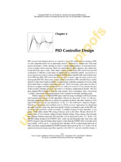
9 Such a controller is called proportional plus integral controller or PI controller . (c) Proportional Integral Derivative (PID) controller . Many industrial controllers employ a proportional, integral plus differential PID regulator arrangement that can be tailored to optimize a particular control system. PID controller is most commonly used algorithm for controller design and it is most widely used controller in industry. The controllers used in industry are either PID controller or its improved version. The basic types of PID controller are parallel controller , serial controller , and mixed controller . The PID controller algorithm utilized for is design velocity algorithm, it is also called incremental algorithm. In the industry, PID controllers are the most common control methodology to use in real applications. PID controller has all the necessary dynamics: fast reaction on change of the controller input (D mode), increase in control signal to lead error towards zero (I mode) and suitable action inside control error area to eliminate oscillations (P mode).
10 Derivative mode improves stability of the system and enables increase in gain K and decrease in integral time constant Ti, which increases speed of the controller controllers are the most often used controllers in the process industry. The majority of control systems in the world are operated PID controllers. It has been reported that 98% of the control loops in the pulp and paper industries are controlled by single-input single output PI controllers and that in process control applications, more than 95%. of the controllers are of the PID type controller . PID controller combines the advantage of proportional, derivative and integral control action. Block diagram of PID controller . de(t ). u (t ) K p .e(t ) K i e(t ).dt K d dt The control signal is proportional to the error signal and the proportional gain K p. A proportional controller will have the effect of reducing the rise time and will reduce, but never eliminate.