Transcription of Comparison of typical 3D printing materials [1]
1 Comparison of typical 3D printing materials [1] ABS Its strength, flexibility, machinability, and higher temperature resistance make it often a preferred plastic for engineers, and professional applications. The hot plastic smell deter some as does the plastics petroleum based origin. The additional requirement of a heated print bed means there are some printers simply incapable of printing ABS with any reliability. It is strong, flexible, with good machinability and a higher temperature resistance. These properties can make it more popular for use in professional applications. It s plastics petroleum based origin cause it to have a less pleasant hot plastic smell. The 3D printer requires a heated print bed for use with ABS. PLA The wide range of available colors and translucencies and glossy feel often attract those who print for display or small household uses. Many appreciate the plant based origins and prefer the semi sweet smell over ABS.
2 When properly cooled, PLA seems to have higher maximum printing speeds, lower layer heights, and sharper printed corners. Combining this with low warping on parts make it a popular plastic for home printers, hobbyists, and schools. Failure testing for 3D printed stage Material Property PLA (Polylatic Acid) ABS (Acrylonitrile Butadiene Styrene) Density (Mg/m 3 ) Young s Modulus E (GPa) Elongation at break (%) 6 3 75 Melting (softening) temperature T m ( o C) 160 88 128 Glass Transition Temperature ( o C) 60 100 Yield Stress y (MPa) 51 Tensile Strength ts (MPa) 36 55 25 50 Ultimate Tensile Strength UTS (MPa) 35 33 110 Fracture Toughness (Plane strain) K IC (MPa m) thermal expansion ( m/m K) 83 95 Strength to weight ratio (kN m/kg) 40 31 80 Shear modulus G (GPa Table 1: Material properties of PLA and ABS [2][3][4] Makerbot Material Properties PLA ABS Standard (STD) High Resolution (MAX) Standard (STD) High Resolution (MAX) Impact Strength (Un notched) IZOD* (J/m) 219 304 331 Compressive Strength (peak) (MPa) 49 Tensile Strength (peak) (MPa) 34 Flexural Strength (peak) (MPa) Table 2: Makerbot material properties chart for PLA and ABS [5] *IZOD impact testing is a standard method of determining the impact resistance of materials .)
3 The results are expressed in energy lost per unit of thickness (such as ft lb/in or J/cm) at the notch. Prototype Stage across the top of stage These two parallel struts on each side of the diamond during translation can be either in tension or compression. As well as this there is a twisting that occurs, creating an s shape. The strut closest to the inside is longer (~ times) that the outside strut so will be affected more. The actual model will have a flat stage on the top and so this will not be a problem. Fast fracture of the material under tensile strain could occur due to crack propagation. The resolution between layers is given as up to 20 microns so it can be assumed that this would be the minimum crack length that would occur in the material. Fast fracture will occur due to crack propagation when fracture toughness K IC equals [4]: KIC=Y a Y=dimensionless constant depending on geometry, typically Y~1 =remote tensile strength a=crack length (Values obtained online for the fracture toughness of PLA and ABS are given above in Table 1.)
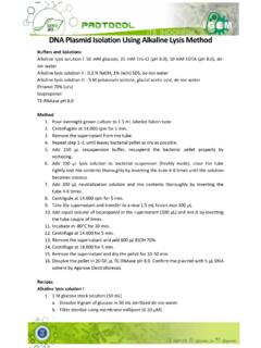
4 Corners at the bottom of the stage If it is assumed that each small strut acts as a cantilever with a weight being applied at the end of it. This can allow for the maximum bending moment and shear stress at the wall to be calculated. This is the point at which the material is being bent and therefore the most likely place of failure. attachments: screws threads will wear away the plastic around it. Experimental testing: 3 point Bending Test carried out on Instron Machine Figures 1 and 2: Test 1 and Test 3 in position within the instron machine at the start of loading. The Instron Machine is a commercial testing machine which is widely used in industry for characterising materials . The material is simply supported on rollers and a load cell applies a force to its center ( and 2). A continuous force is applied until the material fails under the load. A force against deflection (of load cell) graph is plotted which allows the Young s modulus (E) of the material to be calculated using equation 1.
5 E=kL34bd3 Equation 1: k=gradient of linear part of force deflection graph, L=distance between supports, b=width of sample, d=thickness of sample Beams of length 100mm (thickness 3mm, 1mm) and 150mm (thickness , 1mm and 3mm) were used for a three point bending test. printing for 100mm beams, Makerbot, PLA printing for 150mm beams: Ultimaker 2, PLA Infill: 20% Layer resolution: Print speed: 50mm/s Travel speed: 150mm/s Print bed temperature: 72 C Results Load measurement accuracy: of reading Figure 3: Graph of Applied Force against Crosshead Displacement during a Instron three point bend test. Note: error bars are negligible on the graph, the instron machine is a standard commercial machine with high precision. Hysteresis Figure 4: Regions of hysteresis carried out during three point bending test Failure Surfaces Figures 5 and 6: Makerbot sample 1 (t=3mm) and Ultimaker sample 1 (t=3mm) at the end of three point bending test respectively.
6 Table of Results Sample Length (mm) Base (mm) Thickness (mm) Young s Modulus (GPa) 1: Makerbot, PLA 100 20 3 2: Makerbot, PLA 100 20 1 3: Ultimaker2, PLA (3D printed base side down) 150 20 3 4: Ultimaker2, PLA 150 20 3 (3D printed base side up) 5: Ultimaker2: PLA 150 20 1 6: Ultimaker2: PLA 150 20 Table 3: Samples used in three point bending test with corresponding calculated Young s Modulus value. Discussion of Results Comparison was made of samples 1 and 3, the two samples of 3mm thickness, with 1 made using the Makerbot and 3 made using the Ultimaker2 3D printing machines. It can be clearly seen in the graphs in that sample 3 is the stronger sample, it can be loaded to ~4 times that of sample 1 before it begins to fail. The stiffness of sample 3 is ~13 times stiffer than sample 1 (E= compared to ). There is also a difference in the way that the two samples fail under the applied load.
7 With sample 1 it can be seen that the material cracks across the whole sample simultaneously. A brittle, clean fracture surface can be seen in fig. 5. This failure behaviour is also seen in the graph, where the applied load immediately falls to zero. In Comparison to this sample 3 does not actually crack by the end of the test. As can be seen in fig. 6 the cracks try to propagate along the diagonal strips of material, but this orientation prevents the crack from spreading to the edge of the material, and so it tries to propagate along the other direction, producing the zigzag pattern shown. No crack is formed, the material is just elongated at the point of load, weakening the material. The difference in the failure of these two samples is due to the way in which the samples are built up during printing . Both are built from the bottom in alternating layers of oppositely oriented strips of material.
8 The Makerbot lays down horizontal and vertical layers while the Ultimaker2 creates diagonal strips of material, increasing its strength. Sample 3 and 4 are the same sample tested with the base of the 3D printed material facing down and facing up respectively. The sample with the base material facing down was found to be stronger. As the maximum bending will occur at the furthest side from the loading head, it is possible that the base material is strongest when it is printed facing onto the 70 degrees hot plate. This would allow for subsequent layers to melt into the first creating an intertwined lattice formation. As the layers build up further from the hot plate, this would be less likely to occur. The thinner samples (samples 2, 5 and 6) find it hard to hold a load as they are so flexible and so a high enough load is never applied to cause failure. This method of high stress testing may not be ideal for such samples.
9 A hysteresis was carried out during each test as shown in fig. 4. This provided positive results for the use of the material within the microscope. It can be seen that as well as exhibiting linear behaviour on loading the material also unloads and reloads along approximately the same linear line. This shows that the material is not work hardened by bending under the small loads that it would be exposed to within the microscope. No plastic deformation is taking place that could lead to premature failure. For sample 3 a drop can be seen in the graph and then the sample can be seen to be reloaded. This was due to the sample coming off its support during testing but then clicking back into place. References [1] Chilson, L. (2013) The Difference Between ABS and PLA for 3D printing , Available at: updates/the difference between abs and pla for 3d printing / (Accessed: July 2015). [2] Make It From (2015) Polylactic Acid (PLA, Polylactide), Available at: properties/Polylactic Acid PLA Polylactide/ (Accessed: July 2015).
10 [3] Make It From (2015) Acrylonitrile Butadiene Styrene (ABS), Available at: properties/Acrylonitrile Butadiene Styrene ABS/ (Accessed: July 2015). [4] Cambridge Engineering Department (2003) materials Databook, Available at: http://www [5] Makerbot PLA and ABS Strength Data, Available at: , (Accessed: July 2015).