Transcription of Comparison of wind loads calculated by fifteen …
1 Comparison of wind loads calculated by fifteen different codes and standards,for low, medium and high-rise buildingsJohn Holmes1,YukioTamura2,Prem Krishna31 Director,JDH Engineering Research Center, Tokyo Polytechnic University, 1583 Iiyama, Atsugi,Kanagawa, from the Department of Civil Engineering, Indian Institute of Technology, paper describes a Comparison of wind load calculations on three buildings using fifteendifferent wind loading codes and standards from the Asia-Pacific Region. The low-rise buildingis a typical steel portal-framed industrial warehouse building assumed to be located in a ruralarea. The medium-height building is a 48-metre high office building located in urban high-rise building is 183 metres high,alsolocated in urban terrain. The design wind speedsat the top of each building, and other wind properties such as turbulence intensity wereprescribed.
2 The comparisons showed varying degrees of agreement. Comments on thedifferences are 2004 and 2007, four International Workshops on Regional Harmonization of WindLoading and wind Environmental Specifications in Asia-Pacific Economies were held. Apractical outcome of these meetings was a Comparison of the wind loads on three typicalbuildings evaluated by the various wind loading codes and standards across the standards from 15 economies participated in the Comparison ,including the AmericanStandard ASCE 7-02 [1], and the National Building code of Canada [2]. The other documentsused in the Comparison are listed as References [3] to [15]. For some cases, the Eurocode [7]was included in the an initial Comparison ,basicwind speeds were specified at the standard meteorologicalreference position of 10 metres height in flat open terrain.
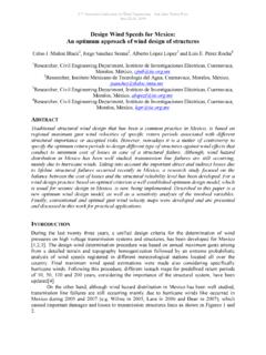
3 However this resulted in very largedifferences in building pressures and responses,with much of the differencesdue to differentterrain and height (profile) specifications in the various comparisonsreported in this paper,design wind speedsat the heightsof thetops of the buildings in the chosenterrainwere speeds with averaging times of 3-seconds, 10-minutes and 1-hourwere all specified, and participants selected the appropriate ones according to the averaging timeused in their own code or standard. For the medium- and high-rise buildings, first mode naturalfrequencies and critical damping ratios were also paper presents the main results of the comparisons and discussessome reasons for thedifferences. The paper is ashorter version of one presented at the Fourth InternationalConference on Advances in wind and Structures(AWAS 08),held in Jeju, Korea, May 29-31, ispresented here for the interest of a wider audience on the eastern side of the BUILDINGThe low-rise building is a typical steel portal-framed industrial warehouse building assumed tobe located in a rural area (Figure 1).
4 Participants were asked to calculate wind loads for thestructural design of the portal frames at the end of the building, a large roller door(3m x 4m) onone wall, and a small window (1m2) on the opposite wall. Internal pressures from a largeopening were included for some wind directions. Design wind speeds at 6m height of 39 m/s, 26m/s and 23 m/s were specified for the averaging times of 3-seconds, 10-minutes, and 1 hour, terrain all around was :Low-rise building (Building 1).Table 1 gives a Comparison of net pressure coefficients across the four faces (A D) of atypical end frame, for SW wind with the large opening(roller door)being considered. Thecoefficients of variation range between 20 and 31%.For the case of a wind parallel to the ridge line, considering the building to be closed (Cpi = 0),the coefficients of variation for the pressure coefficients ranged from 44 to 61%.
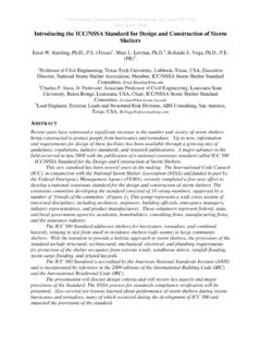
5 Table2 compares the maximum design pressures (or suctions) on the roller door (SW wall) andthe small window (NE wall). The Comparison here is better, the coefficient of variation beingwithin 13 and 26%.Since almost all the parameters have been normalized in this example, the onlyvariable is thecoefficient of pressure, and the variation does appear to be rather large. The only explanationwould seem to be that different standards have sourced different wind tunnel test results onwhich the coefficients have been bays @ 5m=25 mSpan = 15 mNWSET able 1:Net Pressure Coefficients Across Gable Walls wind -SW, Cpi =+ (Large opening in SW Wall) wind SWCountryABCDA ustralia/New Zealand* + of Variation %-312320* shape factors (including area reduction and combination factors)+ including gust factorsTable 2:Maximum wind pressures (+ pressure/- suction) on the 3m x 4m roller door and the 1m2 window, kPaCountryRoller Door(SW Wall)Window(NE Wall) , , , , , , , , , , , , , , , , , , , , , , , , , , , , , , of Variation %13, 1614, 26 ABCDSWMEDIUM-RISE BUILDINGB uilding 2 has horizontal dimensions of 60 m by 30 m with a roof height of 48 m.
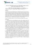
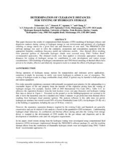
6 The buildingisassumed to beof reinforced concrete construction, with a fa ade consisting of mullions spacedat metres (Figure 2).Figure2:Medium-rise building (Building 2).The building is assumed to be air-conditioned with non-opening windows, and can be assumedto be effectively sealed with regard to internal pressures. The along- wind base bending momentand shearing force were required to be calculated for wind directions normal to the 60 m pressures on window elements near the corners at the top level were also 3-second, 10-minute and 1-hour wind speeds at the top of the building were specified as 56m/s, 36 m/s and 33 m/s respectively, and a turbulence intensity of at the top of the buildingwas assumed. The resonant response for this building was required to be considered by somecodes and standards, and, for this purpose, the first-mode natural frequency of Hz, andcritical damping ratio of 2% were calculated values for along- wind base shearsQand base bending momentsMare shown inTable3 and compared in Figure 3.
7 It may be a matter of course thatQ andM show a clearcorrelation. Indonesia[13]shows the highest values, (7,477kN and 210 MNm), and China[8]shows the lowest combination, (3,282 kN and 99 MNm). The Indonesian values are more thandouble the Chinese values. The coefficient of variation is estimated at 22% for boththe baseshear and the base bending moment. Considering the given harmonized condition specifying thesame design wind speed at the top, the coefficient of variation, 22%, is larger than (draft standard), Vietnam [15], Australia/New Zealand [12], Malaysia [9], andIndonesia compose a higher magnitude group (see Circle A in ). Japan [3], Korea [11[ andCanada[2](Circle B), India [6] and Hong Kong [5] (Circle A ) and the Philippines[4]composea medium magnitude [10] and Taiwan [14] (Circle C ), the [1] and China[8]compose a lower magnitude group.]]
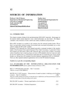
8 The US and the Philippines are in Circle C. These groupsclosely correspond to several groups related to their origins, as mentioned in the next section forBuilding shows the cladding pressures on window elements near the corners at the top level. Thecoefficients of variation for positive cladding pressures and negative cladding pressures are48m30m60mestimated at 22% and 23%, and are similar to those for along- wind base shears and base : Along- wind base shears and bending moments for Building 2 Country/RegionCode/StandardBase ShearQ (kN)Base BendingMomentM( )Australia/New : 20025,727150 CanadaNBNBCC (2005)5,332142 ChinaCHGB50009-20013,28299 Hong KongHKCP-20044,573116 IndiaINIS875(Part 3)-19874,957131 IndonesiaIASNI-03-17277,477210 JapanJAAIJ-RLB-20045,061132 KoreaKOKBC (2005)5,534134 MalaysiaMAMS1553-20025,698152 PhilippinesPHNSCP-20015,026128 SingaporeSI(draft)6,556163 TaiwanTATBC3,738100 ThailandTHEIT-1018-463,73797 United StatesUSASCE 7-054,108117 VietnamVITCVN2737-19956,423165 Mean5,149136 Coefficient of Variation(%)2222 EurocodeEU6,042182 Figure 3.
9 Relation between base shear and base bending moment for themedium-rise building (Building 2).01,0002,0003,0004,0005,0006,0007,0008 ,000050100150200250 Base ShearQ (kN)Base Bending MomentM (MNm)IAEUSIVIMAANNBKOCHTATHUSHKINJAPHAA BCC QmeanMmeanTheVietnamNorm [15]shows the highest positive cladding pressure, , but the highestnegative ( lowest magnitude) pressure, China shows the lowest positive claddingpressure, , and a relatively high negative pressure, , a lax theother hand, Australia/New Zealand, Malaysia, Indonesia and Singapore (Circle A)as a groupderived from the same source, show the most unfavorable combination of positive and negativepressures, such as ( and ).Table 4: Cladding pressures for Building 2 Country/RegionCode/StandardPositiveCladd ing PressureP+ (kPa)NegativeCladding PressureP (kPa)Australia/New (2005) (Part 3) (2005) (draft) StatesUSASCE of Variation(%) BUILDINGThe high-rise building was 183 metres high, with horizontal dimensions of 46 m and30 mlocated in urban terrain (Figure 4).
10 This building was previously used as a benchmark testbuilding for aeroelastic wind -tunnel tests, known as the CAARC Building [16]. The buildingwas assumed to have an average density of 160 Kg/m3, and natural frequencies in both swaydirections of Hertz. The sway mode shapes were assumed to be linear. The structuraldamping, as a fraction of critical, was specified to be for ultimate limit states (base shearand bending moment), and for serviceability limits states (accelerations at the top of thebuilding). For wind directions normal to the 46 m wall, base bending moments and shears, andpeak accelerations at the top of the building, were required to be calculated . Both along-windand cross- wind responses were calculated , when the particular codes and standards allowed thesecalculations to be made.