Transcription of Complex Clocking Situations Using PrimeTime
1 Complex Clocking Situations Using PrimeTime Paul Zimmer Cisco Systems 1450 North McDowell Blvd. Petaluma, CA 94954-6515. Introduction Years ago, before I starting working on telecommunications chips, I used to advise other designers, Never use the falling edge of the clock, never use divided clocks, and never mux clocks except for scan . This is still sound advice most of these techniques should be avoided if possible. But in the telecommunications world, you just can't avoid doing these things. In the 3 years I've spent in the telco world, I have done static timing on 5 chips, and they all had multiple edge usage, muxed clocks and divided clocks.
2 Worse, most had circuits that did combinations of these things. Over time, I have developed some techniques for handling these Situations that I thought might interest other designers. Those that do these sorts of chips for a living may already be familiar with much of what I will present, but hopefully designers who only occasionally have to deal with these sorts of problems will find some handy shortcuts here. Handling Clock Muxing When dealing with muxed clocks, it is important to do set_case_analysis on all controlling points to force the muxes into a known state.
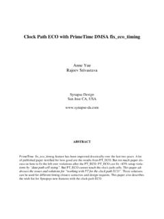
3 There are several reasons for this: 1) For a mux between two clocks, PT will not time both paths. It will time only the path involving the clock most recently created! 2) For a mux between two versions sourced by a common clock (for example, the raw clock and a delayed clock), PT will choose the worst possible scenario (data launched with the delayed clock and sampled with the raw clock for setup calculation, for example). Here's an example. This is a simple circuit involving a muxed clock: SNUG San Jose 2001 2 Complex Clocking Situations Using PrimeTime Read in the netlist, and do the following sequence of commands: create_clock -period [get_ports bpclk].
4 Create_clock -period [get_ports lineclk]. report_timing -to [get_pins f2_reg/D]. Since PrimeTime normally chooses the worst case for analysis, you would expect the timing report to use the faster clock, and check against a 10 ns period. Unfortunately, this is not the case. Instead, the result looks like this: report_timing -to [get_pins f2_reg/D] : Startpoint: f1_reg (rising edge-triggered flip-flop clocked by lineclk). Endpoint: f2_reg (rising edge-triggered flip-flop clocked by lineclk). Path Group: lineclk Path Type.
5 Max Point Incr Path ---------------------------------------- ----------------------- clock lineclk (rise edge) clock network delay (ideal) f1_reg/CP (FD1QA) r f1_reg/Q (FD1QA) f f2_reg/D (FD1QA) f data arrival time clock lineclk (rise edge) clock network delay (ideal) f2_reg/CP (FD1QA) r library setup time data required time ---------------------------------------- ----------------------- data required time data arrival time ---------------------------------------- ----------------------- slack (MET) Oops! We've got a 10ns path being checked as a 200ns path!
6 If we do the create_clock commands in the opposite order: create_clock -period [get_ports lineclk]. create_clock -period [get_ports bpclk]. report_timing -to [get_pins f2_reg/D]. SNUG San Jose 2001 3 Complex Clocking Situations Using PrimeTime We get the 10ns check: report_timing -to [get_pins f2_reg/D] : Startpoint: f1_reg (rising edge-triggered flip-flop clocked by bpclk). Endpoint: f2_reg (rising edge-triggered flip-flop clocked by bpclk). Path Group: bpclk Path Type: max Point Incr Path ---------------------------------------- ----------------------- clock bpclk (rise edge) clock network delay (ideal) f1_reg/CP (FD1QA) r f1_reg/Q (FD1QA) f f2_reg/D (FD1QA) f data arrival time clock bpclk (rise edge) clock network delay (ideal) f2_reg/CP (FD1QA) r library setup time data required time ---------------------------------------- ----------------------- data required time data arrival time ---------------------------------------- ----------------------- slack (MET)
7 But the correct way to do this is to do set_case_analysis on the mux control signal (sel_line): create_clock -period [get_ports bpclk]. create_clock -period [get_ports lineclk]. set_case_analysis 0 [get_ports sel_line]. SNUG San Jose 2001 4 Complex Clocking Situations Using PrimeTime Now we get the correct calculation regardless of the order of clock declaration: report_timing -to [get_pins f2_reg/D] : Startpoint: f1_reg (rising edge-triggered flip-flop clocked by bpclk). Endpoint: f2_reg (rising edge-triggered flip-flop clocked by bpclk).
8 Path Group: bpclk Path Type: max Point Incr Path ---------------------------------------- ----------------------- clock bpclk (rise edge) clock network delay (ideal) f1_reg/CP (FD1QA) r f1_reg/Q (FD1QA) f f2_reg/D (FD1QA) f data arrival time clock bpclk (rise edge) clock network delay (ideal) f2_reg/CP (FD1QA) r library setup time data required time ---------------------------------------- ----------------------- data required time data arrival time ---------------------------------------- ----------------------- slack (MET)
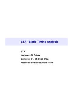
9 Note that Situations like this can be readily found in PrimeTime Using the check_timing . command. These show up as multiple clock warnings. Prior to doing the set_case_analysis, check timing produced the following: Warning: There are 2 clock pins which are driven by multiple clocks. This warning disappears after the set_case_analysis has been done. In general, I recommend making it part of your standard flow to clear all warnings from check_timing before proceeding with the rest of the script. SNUG San Jose 2001 5 Complex Clocking Situations Using PrimeTime Here's an example of the other case.
10 This is a simple circuit involving a programmable clock delay. Read in the netlist, and do the following sequence of commands: create_clock -period [get_ports clk]. set_propagated_clock clk set_annotated_delay -cell -from dly/A -to dly/Z. (The set_annotated_delay is just to make the example easier to follow. By forcing a known delay on the dly cell, it's easier to see what's-what in the timing report). SNUG San Jose 2001 6 Complex Clocking Situations Using PrimeTime If you report_timing to the second flop ( Using path_type full_clock), you get this: report_timing -to [get_pins f2_reg/D] -path_type full_clock Startpoint: f1_reg (rising edge-triggered flip-flop clocked by clk).