Transcription of Composite Fan Blades and Enclosures for Modern Commercial ...
1 Composite Fan Blades and Enclosures for Modern Commercial Turbo Fan Engines Joshua Fromm ASEN 5063: Gas Turbine Propulsion 1 | P a g e Abstract Composite materials are currently found in a handful of Commercial turbo fan engines, such as the GE90 and GEnx engines. The desire to reduce weight, increase efficiency and decrease cost has driven engine designers to consider composites, mainly carbon and Kevlar , when choosing materials for fan Blades and cases. Research began in the mid 70 s and continues through today, with manufacturing and analysis tools constantly improving. The main considerations in the design of fan Blades are efficiency, weight, and durability. The Blades must be capable of withstanding common debris ingestion with no damage, and be easily repaired and maintained. Composites have allowed increased efficiencies by allowing more complex shapes, resulting in fewer Blades , and less weight.
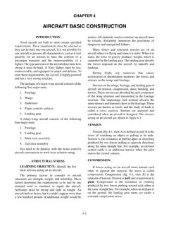
2 In terms of the fan case, blade containment and weight are the most important factors. The case must be able to withstand a worst-case blade-off scenario, and not permit any fragments from penetrating the case. Composites have been shown to be a very acceptable material choice to construct the single most massive component of an engine . The most Modern Composite engine , the GENX has saved over 350 lbs per engine , along with higher efficiencies by employing the use of carbon composites. At the time, it serves as the pinnacle of jet engine Composite use. Introduction The purpose of this research paper is to take a closer look at the types of Composite fabrics used in Modern engines, along with the manufacturing and testing techniques used to analyze these Blades . The two main components researched were the main engine fan Blades and the fan casing, which protects the passengers from broken blade fragments, should it occur.
3 In addition, a couple future uses of composites in engines were seen. Composites The term Composite can mean any of a thousand things in today s world. However, when talking about turbofan engines, only the best materials are considered. Composites in this case usually refer to variations of carbon fiber, Kevlar and fiberglass. Composites are used primarily for their high strength-to-weight ratio and highly customizable properties. Essentially, if you want say 10% of your strength to be in one direction and 90% to be in another, arrangement of Composite plies can satisfy this requirement, with no penalty to mass as would occur with metals. The other important separation between composites and their metallic counterparts is the manufacturability. Because the fibers are actually flexible before being cured, very complex 2 | P a g e shapes and contours can be easily made, and quickly reproduced with the help of molds.
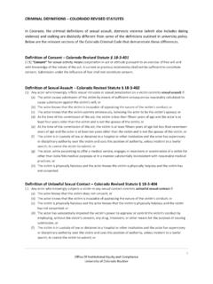
4 This capability allows designers to model even more efficient Blades than ever before. There are many types of carbon fiber. The figure below shows two of these types. The image on the left is a close-up of a twill-weave 3K tow and the image on the right shows a unidirectional fabric, held together with a small amount of hot-melt type glue. These are the very basic forms of carbon fiber fabric. Kevlar and fiberglass also come in similar forms. Figure 1: Carbon Fabric The design of mass and strength critical components, such as fan Blades , requires the designer to orient the fabrics in very specific directions. For this reason, unidirectional carbon tow is generally used for fan Blades . Figure 2 below illustrates how uni-directional tow can be layered together for desired performance. Figure 2: Multi-layer Carbon This is somewhat less important for a fan case, which sometimes allows designers to use the pre-woven fabric for its multi-directional properties.
5 3 | P a g e Figure 3: Fan blade layup schedule Figure 3 above shows how complex the fiber directions and layer sizes can be for a fan blade. These layers have been determined both by trial and error and actual computer simulations. Both centrifugal and aerodynamic forces must be considered, along with impact resistance to withstand foreign object ingestion. Naturally, composites are not the fix-all miracle. Current composites are generally not used in higher temperature applications due mainly to the epoxy resin used. The maximum operating temperature can sometimes be increased by using a polyimide based resin. For this reason, Commercial systems have limited composites to fan Blades and fan cases. Fan Blades Composite fan Blades are without question one of the greatest innovations in fan blade technology. Carbon fiber is on the order of times less dense than the Titanium used on older fan Blades .
6 Although this does not compute to 1/3 the weight, the system weight is considerably reduced with the use of composites. Additional advantages are seen from the stiffness of composites, resulting in much tighter tolerances, thus increasing efficiency. The tighter tolerances, combined with the workability of carbon fiber result in a highly optimized blade that improves performance so greatly even fewer Blades are needed. Figure 4 below illustrates one of the GEnx fan Blades , one of the most advanced fan Blades in history. 4 | P a g e Figure 4: GEnX Fan Blade One major advantage to composites is the ability to construct very complex curvatures and shapes. The result is a highly optimized blade that is no longer constrained by manufacturability. One of the major design considerations, beyond the obvious structural requirements, is impact resistance.
7 During normal operation, turbine engines tend to ingest gravel from the runway, birds, and heavy weather such as hail. The fan Blades must be capable of withstanding these foreign objects, within reason. Figure 5 below suggests that a 2lb bird can apply a force of over 1500 lbs at impact speeds. Figure 5: Impact force vs. Impact time Trial and error has led to many of the Modern fan blade improvements. The picture above is of a blade tested by NASA that did not contain a leading edge reinforcement. The blade had ingested a lb soft bird. The results were considered unacceptable. The paper(REF 5) concluded that leading edge reinforcement techniques needed to be investigated. Since this time, titanium leading edges have been integrated into the Composite layup of the fan Blades . 5 | P a g e Not only is the goal to prevent failure of the blade due to small debris, but also to improve the reparability of the blade should it impact debris.
8 Reparability has always been an inherent weakness of Composite components. Chemical and UV resistance were also concerns with these Blades . engine fluids (such as fuel and oil) along with UV radiation can breakdown the epoxy resin. The solution to this problem was to simply put a protective polyurethane coating on the Blades . Unfortunately, the Modern fan Blades found in the GEnx are still a highly protected trade secret, so further details are difficult, if not impossible to obtain. Fan Case The fan case of a turbo fan engine is a major part of the engine that serves two purposes; enclose the fan, and shield the passengers and aircraft in the case of a blade-out accident. More often than not, the case is the single heaviest component of a jet engine . For this reason alone, optimal designs that reduce weight are absolutely critical. Figure 6 below shows a cut-away view of the GEnx engine .
9 As might be expected, the fan case is the large cylinder covering the fan unit. The blue highlighted ring is the section that protects the passenger from blade fragments. Figure 6: GE GEnX engine cut-away (GE website)2 6 | P a g e Figure 7 below shows an actual GEnx engine on the final assembly line. It is difficult to say for certain what exactly the Composite case is made of, as it is still a trade secret, but visual inspection suggests that a 3D tri-axial carbon fiber weave is used, at least on the exterior of the case. Figure 7: GE GEnX engine (GE website)2 One of the most important considerations in the design of the fan cases on these Commercial turbo fans is a blade-off scenario. This scenario covers everything from a blade breaking loose at the hub-joint (worst case) to a blade fragment caused by foreign object ingestion. The fan case must be made to contain the blade in all cases in order to protect the passengers of the aircraft , and the aircraft itself.
10 A standard factor to choose the material is based on the amount of energy absorption (from a blade fragment) per unit mass (Ref. 4). As mentioned earlier, these fan cases are the single most massive part of a turbo fan engine . Thus, the second most important aspect of these cases is weight (Ref. 1). For this reason, Composite materials were investigated as a possible solution to the weight problem. Figure 8: Undesirable Case-Blade Interaction4 7 | P a g e Figure 9: Desired Case-Blade Interaction4 Figure 8 and Figure 9 above show the basic mechanics of a blade-off scenario. The first two pictures show a rigid and soft case. The rigid case causes a domino effect of blade failures due to interference with the path of the broken blade. In a soft case the non-damaged Blades will be forced to rub on the casing due to small clearances. Both of these cases are highly undesirable due to the increased damage.